Mini Drill Press

Status
Not open for further replies.
Messages
242
Reaction score
2
Location
Canada, AB, Spruce Grove
So all I need is
  • 4 - PTFE bushings (10mm)
  • 2 - 10mm precision steel rods on ebay (~ 200mm long each)
  • 4 - Bearings
  • 200cm(squared) (I'll need more for the spines) - MDF
  • 2 - Springs

Sound about right?
 

itsid

Moderator
Staff member
Messages
11,563
Reaction score
247
Location
Ruhrpott [Germany]
translation error ;)
no ptfe bushings, but ptfe linear bearings...

linear ptfe bearings (ebay #400434689543 for example)
do not buy ptfe bushings ( ebay #131112919384)

so it's
  • 4 - PTFE bushings (10mm)
  • 2 - 10mm precision steel rods on ebay (~ 200mm long each)
  • 200cm² - MDF
  • 2 - Springs *

*maybe one spring will do ;) depends on what you have and how/where you attach it.

sounds about right, yes

'sid
 
Messages
242
Reaction score
2
Location
Canada, AB, Spruce Grove
translation error ;)
no ptfe bushings, but ptfe linear bearings...

linear ptfe bearings (ebay #400434689543 for example)
do not buy ptfe bushings ( ebay #131112919384)

so it's
  • 4 - PTFE bushings (10mm)
  • 2 - 10mm precision steel rods on ebay (~ 200mm long each)
  • 200cm² - MDF
  • 2 - Springs *

*maybe one spring will do ;) depends on what you have and how/where you attach it.

sounds about right, yes

'sid

Oh I see, thanks! :cheers2:

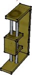
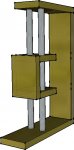
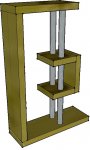
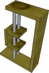
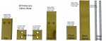
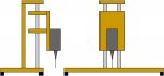
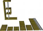
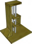
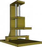
I made a 3d design in Google Sketchup. I didn't add the springs or other little gizmos because that's just too complicated for me in this program, or any program. Simple, easy, and nice looking. The motor just mounts on the front plate but I don't know how I want to mount it just yet. Maybe a latch of some sort so I can also take the motor off for a handheld tool. I also got a buddy of mine working on a design for the metal mini drill press I posted above (The nice looking one). So I'm going to tackle that one after I do this one.

Anyways here are the pics. What do you think? I noticed this site doesn't allow PNG files for attachments. How come?
 

Attachments

  • SketchUp 2014-02-19 11-12-49-48.jpg
    SketchUp 2014-02-19 11-12-49-48.jpg
    15.6 KB · Views: 0
  • SketchUp 2014-02-19 11-15-06-51.jpg
    SketchUp 2014-02-19 11-15-06-51.jpg
    49.3 KB · Views: 0
  • SketchUp 2014-02-19 11-16-22-75.jpg
    SketchUp 2014-02-19 11-16-22-75.jpg
    73.6 KB · Views: 0
  • SketchUp 2014-02-19 11-18-02-49.jpg
    SketchUp 2014-02-19 11-18-02-49.jpg
    79.6 KB · Views: 0

itsid

Moderator
Staff member
Messages
11,563
Reaction score
247
Location
Ruhrpott [Germany]
Nice...

But, take care to use a smaller distance from the backplate to the rods
(go as small as possible here)
The main reason is, that it's MDF you're working with, and no matter what connection you use on the top edge, it's going to get weak.
Or add sidewalls to stiffen the frame.

I'd say find some pipe clamps like this:
http://www.ebay.com/itm/ZSI-Beta-Cl...128?pt=LH_DefaultDomain_0&hash=item35ccecedd0
they come in different diameters and I think at least a bigger one should hold your motor just nicely ;)

'sid

PS yes please PNG support would be nice ;)
 
Messages
242
Reaction score
2
Location
Canada, AB, Spruce Grove
Thanks for the tip, I'll bring back the two rods just before the wooden slide touches the back plate. Or maybe a side plate... I have't decided yet. If I had a side plate I wouldn't make it go any further then the steel rods themselves so I don't limit myself to how much room I have for the PCB to lay on. So I think I will do a side plate since I don't want to have to go through the trouble of redesigning this thing :lolgoku:

Here's the dimensions, side plates not included as I haven't made them yet. Do they seem appropriate? I made some changes to what you gave me.
 

Attachments

  • SketchUp 2014-02-19 16-25-12-96.jpg
    SketchUp 2014-02-19 16-25-12-96.jpg
    37.4 KB · Views: 6

itsid

Moderator
Staff member
Messages
11,563
Reaction score
247
Location
Ruhrpott [Germany]
Don't forget that you cannot move the PCB past the metal rods anyways.
So no matter how long your top and bottom parts are, the slider parts must be short (for stability.. you can't just add sidewalls to the slider, at one point you have a catching leverage.
And that's all that is providing the space between the rods and the drillbit itself.

So you have to think of a way to lift the whole assembly enough for the PCB to slide under it (doesn't need to be much for an average unpopulated pcb)
a wide cutting board on four 6mm high feet for example.
on it's lowest point the drill will get past that I am sure ;)

If not you can still enlarge the front spine to say 100mm length and have one half of that protrude the back spine ;)

like this:
pcb drill.jpg
(for better contrast with backspine removed in frontview)

'sid
 
Messages
242
Reaction score
2
Location
Canada, AB, Spruce Grove
Enlarge the front spine? I see. I think I'd rather just add a handle onto the right side of the slider so I can hold that and push i down against the resistance of the two (Maybe even four) springs. Altough, now that I think about it I might have to increase the size of the front spine... Since it's already 70mm (7cm) I could double it's length. That should be good. I really can't be sure until I get the drill bit part of the kit and attach onto my motor so I can measure the total length. Although I think 140mm is far more than enough.

I must thank you for all the help, sid. I don't think I could have ever plan this without your input.
 

Poboy kartman

Senior Moments Member
Messages
12,461
Reaction score
69
Location
White Settlement Texas
I think I would design this quite differently but I have one question and one major flaw- ( to my way of thinking. ..) why is the bottom plate ( that rides on the rods ) so high up allowing leverage and any deflection/ slop to multiply? Could that plate/arm not be just above the chuck?
 

itsid

Moderator
Staff member
Messages
11,563
Reaction score
247
Location
Ruhrpott [Germany]
my last pic is exaggerated, to make the point of a longer plate.

Of course there is no need to have another 3" travel downwards when the drill hit the table already ;)

The ideal would be: the plate hits the pcb, the drill is just long enough to drill completely through,
and that's all happening near the lower end of travel.

To be honest, for a pcb drill you'll never need 4" of travel,
but we all know, once you have such small drill, it's not only PCBs you're going to put under it,
so having some extra (since it nearly costs nothing) only adds versatility ;)

'sid
 
Messages
242
Reaction score
2
Location
Canada, AB, Spruce Grove
Poboy kartman said:
I think I would design this quite differently but I have one question and one major flaw- ( to my way of thinking. ..) why is the bottom plate ( that rides on the rods ) so high up allowing leverage and any deflection/ slop to multiply? Could that plate/arm not be just above the chuck?
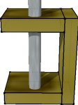
Do you mean the sliding plate? The bottom one? Like this one?
SketchUp 2014-02-19 18-35-37-85.jpg
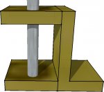
Well I'm not sure what you mean really. It's height will vary since it will go up and down but I think your talking about something else. Do you mean extend and arm off of the spine instead of making the spine longer? Like this?
SketchUp 2014-02-19 18-40-53-30.jpg
Like say attach the motor onto that extended piece and drill a hole allowing the chuck, but not the motor, to go through that hole.
 

Poboy kartman

Senior Moments Member
Messages
12,461
Reaction score
69
Location
White Settlement Texas
Do you mean the sliding plate? The bottom one? Like this one?
View attachment 45216
Well I'm not sure what you mean really. It's height will vary since it will go up and down but I think your talking about something else. Do you mean extend and arm off of the spine instead of making the spine longer? Like this?
View attachment 45217
Like say attach the motor onto that extended piece and drill a hole allowing the chuck, but not the motor, to go through that hole.

Exactly- and looking closer to what I would do all the time- but still aways off....
 
Messages
242
Reaction score
2
Location
Canada, AB, Spruce Grove
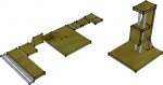
Moved the sliding piece back closer to the back spine. I think it turned out well and it allows more space for the PCB board to sit on the bottom plate. I think I'll make the bottom plate a square instead of a small rectangle in order to make it more stable when it stands. Maybe even add foot pegs that are resistant to sliding.

Anyways, here's a picture of what I changed. No dimensions yet, but will add later when I finish making changes.

Edit: Changed it some more in the last two attachments to make it a bit more structurally sound. For the triangle at the back, I may just use a piece of metal junk that I have in the basement somewhere.

Edit Again: So I just talked to my electro tech teacher and he said that we could build this in class :D I would also get a credit for this. All I need to do is supply the metal bars and a way to attach the drill bits which I can get from that eBay link I posted somewhere above in this thread. I just have to do a write up of what it needs in order to be built or it won't work so luckily for me, we already have that done :D I won't have it done in time to drill the PCB boards I'm making in class but that doesn't matter. I'm excited and building will take place next week or the week after, hopefully.

So before I get started, do you see any modifications I might want to consider? Besides the one that Poboy kartman Poboy kartman suggested? I'm still going to add his suggestion.
 

Attachments

  • SketchUp 2014-02-20 08-01-50-32.jpg
    SketchUp 2014-02-20 08-01-50-32.jpg
    90.4 KB · Views: 1
  • SketchUp 2014-02-20 12-03-33-49.jpg
    SketchUp 2014-02-20 12-03-33-49.jpg
    72.1 KB · Views: 4
  • SketchUp 2014-02-20 11-58-05-67.jpg
    SketchUp 2014-02-20 11-58-05-67.jpg
    49.7 KB · Views: 4
Messages
242
Reaction score
2
Location
Canada, AB, Spruce Grove
Ordered the drill chuck!

Now I just have to go to Home Depot and get the rest of the stuff I need. I think I'll wait until the chuck arrives to do that.

Now for another question.

About the bearings. Do I just push them into the 10mm holes that I drill in the sliding piece and then put the steel rods in the bearings' holes? Wouldn't the bearing holes be smaller than 10mm since the outer diameter of the bearings are 10mm? So wouldn't I need <10mm steel rods? Or am I confusing myself.
 

itsid

Moderator
Staff member
Messages
11,563
Reaction score
247
Location
Ruhrpott [Germany]
the ID is 10mm the OD is 12, that's why two holes you must widen to 12mm.
I had very good success by just pushing them in, the OD steel on MDF is enough frictionwise to keep em in.

If for some reason you had your holes a little too large,
just apply some glue to the outside before pressing them in.

you remembered that you cannot move a pcb pass the steel rods, don't you?
that's why I suggested the legs on the bigger base plate (post #26),
(pcb goes under the baseplate, to pass the rods) and the actual slider to be on the very edge. to allow the drillbit pass the baseplate.
just keep in mind that you shouldn't move the drill motor too far from the rods,
to prevent it from catching due to the weight and lever.
And second that you cannot drill holes further away from the edge, as the drillbit is away from the steel rods in your design.

But I'm sure you got that already. ;)

'sid
 
Messages
242
Reaction score
2
Location
Canada, AB, Spruce Grove
I see what you mean, thanks for the clarification. I think I will change the design again sometime over the next few days to allow the PCB to go under the board. That seems a lot easier. The motor isn't super far from the rods, only 5 cm at most.

Thanks for helping me design this. Once I get everything set up and made, I'll give anyone and everyone who helped me along the way a copy of these plans, free.

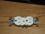
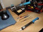
Edit: Temporary power supply is a AC-DC converter that gives out 12V 3.5A. It's basically just an old Nintendo Wii Adapter that I had as a spare. I cut off the part that plugs into the Wii and saved it in case I ever need to re-wire the adapter back into the Wii if my other one breaks, which is highly unlikely. So I was thinking, "I want to make this thing both battery and wall powered." Why not right? I could use the battery as a backup power just in case I ever want to make it portable. That way it can be both portable and stationary. Plus I don't want to have to use the battery I have right now since it's for my motorcycle and I don't want to have to charge it from draining it due to using it as a test battery. Another perk is that this adapter will give me a promised 12V. I could use one of these bad boys to swap between the power sources
DSCF0341.jpg
 
Messages
242
Reaction score
2
Location
Canada, AB, Spruce Grove
What if I just did this instead of making the PCB go under the board? Yes, it would still be limited in size, but I won't be making any complex PCBs whereas I need a lot of space.
 

Attachments

  • SketchUp 2014-02-26 15-34-01-83.jpg
    SketchUp 2014-02-26 15-34-01-83.jpg
    66.6 KB · Views: 0
Messages
242
Reaction score
2
Location
Canada, AB, Spruce Grove
Maybe once this is done I'll build this :stir:

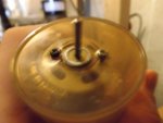
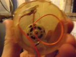
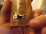
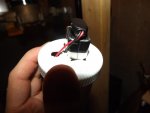
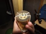
Edit: So, I got bored of waiting for my drill chuck to arrive, so I decided to make a hand held version of my drill press. This one is pure battery powered, but if I wanted, I could hook it up to a 9-18V DC wall wart. I used my original 9-18VDC super-speed motor. 24,000 RPM, no load. Maximum 4.2 Amps motor. It uses 9V DC via a battery and is hooked up to a switch for on and off convenience. I still can't put bits onto this one since I haven't gotten my chucks (I ordered two). After I drilled and carved holes into the pill bottle's lid, it was no longer able to lock on like it used to. To solve that issue, I screwed some elastic bands under the screws (The screw prevent the motor's shaft from going back into the case) and made them going up and around the battery.

It doesn't have much power since it's only 9V, but this only took me an hour to make since I was making it with no pre-made plans or ideas. I hooked it up to 12V you can just hear and feel the difference in power.

Here are the pictures!
 

Attachments

  • DSCF0346.jpg
    DSCF0346.jpg
    53.9 KB · Views: 2
  • DSCF0347.jpg
    DSCF0347.jpg
    56.6 KB · Views: 3
  • DSCF0348.jpg
    DSCF0348.jpg
    51 KB · Views: 3
  • DSCF0349.jpg
    DSCF0349.jpg
    38.8 KB · Views: 3
  • DSCF0350.jpg
    DSCF0350.jpg
    49.2 KB · Views: 3
  • DSCF0351.jpg
    DSCF0351.jpg
    44.7 KB · Views: 3
Status
Not open for further replies.
Top