Lights and other elec. device mounting/wiring?

mckutzy

Well-known member
Messages
8,353
Reaction score
109
Location
bc, canada
I decided I could do without the through hole Gland, through the mirror mount... It would be cleaner... but I cant really find anything right now...Ill wait I guess...

In the mean time... I found an easier rout, that is, through the fender gap of the door...
No holes to drill... It seals by the door gasket, and routs inside nicely...
Im still working out the side vents in the defrost, but the top works like it should. So for now Ill leave out the vent deflectors and leave it as is...
I Soldered the connections( give a lower profile for shrink) and then shrinked individually and over the joint as a whole....I then found some long length shrink tube, and sleeved/Shrinked it over the joint to seal the outside, and along the length leaving a few inches for the power-in connections. I didnt have much for any other sleeving material... so that will do for now... Should be water resistant for a good while...
Powered up and it worked... Looks good too.... Have to wait for a darker time and Ill test in the darker road or wait till I go to work in the morning.... Either way.. Im happier...
 

Attachments

  • image.jpg
    image.jpg
    281.1 KB · Views: 9
itsid

Moderator
Staff member
Messages
11,563
Reaction score
246
Location
Ruhrpott [Germany]
exposed wires are prone to be cut by idiots,
uv-rot by sunlight,
or internally rust by rain and frost (do not underestimate capillary effects)
Sooo.. for a brief period of time, sure..
for a permanent solution, I'd vote for "Nope!"

'sid
 

itsid

Moderator
Staff member
Messages
11,563
Reaction score
246
Location
Ruhrpott [Germany]
But that had me thinking..
is there enough wire to take the long 'manufacturer' route?
that is
mirror into the door, down the inside to just below the upper hinge, through the tunnel, into the chassis and up to the dash board again?

'sid
 

mckutzy

Well-known member
Messages
8,353
Reaction score
109
Location
bc, canada
It isnt an electric adjustable mirror. So the outer bucket just contains the mirror support, the bracket mount is solid, an no way into the door/cab...
I did think of that aswell... hide the wire along the edge of the mirror and into inside... but thats when it came down to drilling into the mirror mount as there is a clean passthrough into the cab.
 

Functional Artist

Well-known member
Messages
5,596
Reaction score
3,202
Location
Toledo, Ohio
IIRC that type of mirror is connected to the door with (3) bolts (from the inside)
…& the door itself should have a hole for the wires for power/heated mirrors (even if not equipped with that feature/option)

I think what Sid is suggestin' is to drill a small hole (just big enough for the wire) into/thru the (triangular shaped) mirror mounting/housing
...then, run the wire thru/inside of the door etc. :thumbsup:

Which would make for a safe'er, more protected & a cleaner look :cheers2:

Short, sweet & to the point :2guns:
 

itsid

Moderator
Staff member
Messages
11,563
Reaction score
246
Location
Ruhrpott [Germany]
yeah essentially.. a small hole for the wire to get into the plastic mirror housing

I thougt it had a lever to adjust the mirror from the inside..
so there's still a passthrough there ..

and tbh I was expecting electric windows (so there'd be a tunnel to the door)
at least there should be plastic caps where the tunnel would be between door and chassis..

*shrugs*

'sid
 

mckutzy

Well-known member
Messages
8,353
Reaction score
109
Location
bc, canada
The tunnel exists in the door frame... Behind the mirror mount...and a trim cap inside..
The pathfinder d22 typically has adjustable from inside mirrors, electric or lever steer... The same doors of the same family...
 

mckutzy

Well-known member
Messages
8,353
Reaction score
109
Location
bc, canada
Round 2... Ding ding ding.... Fight......

Well... I finally got all my crap together and got the ditch light onto the "new" truck...
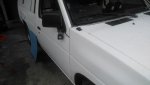
After the dumb road rager kill my last D21 a few months ago, I managed to get another d21 with about half the amount miles(KM's actually), an earlier model, 1989. Same color, long box, unfortunately no bucket seats, but I might get some later on... The bench is kinda growing on me, but I really liked the console armrest I made for the first truck, and have another ammo can for that aswell.

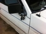
I did get a few thing off of the truck before the insurance company took it... I got my light that I made the mount for on the mirror above...

I made a new bracket exactly the same using the same template I made earlier. Mounted up the same way.
I didnt have a side post battery this time, so I couldnt use the battery mount fuse block like before. So I used a fuse tap till I get a better fuse block setup..

This time, Im just going for the one light on the right side(I had wired up for both sides on the other, but didnt get it mounted cause I didnt need it so much, but still have that mount from previous should I need).

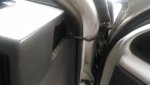
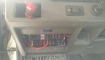
Ran a power and a remote ground for the light and another for the lighted switch. Linked up with the light in same fashion through the side vent hole. Tucked and zapped to keep tidy and away.

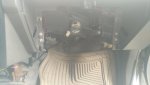
I also fixed the power socket for the cig adapter. I guess the PO or down the line someone had cut that off the power from the plug and left it hanging, using that for the radio power instead.

Having a bunch of experience with fitzing around with the radio and dash in the last year, I recognized instantly what the plug exactly was for when I removed a lower molding piece...
I had to fix the terminal with a new piece of wire, as it was cut off short. I unfurled the stub, re-soldered crimped and shrinked to reuse the terminal as it was an automotive variant... Not a common from the parts store.
Got it all buttoned up.... Radio works, my fans work, powered from the cig power port, and my new ditch light.... I have to wait till later for the night test, but all looks good..
 

Attachments

  • IMG_20200128_101434.jpg
    IMG_20200128_101434.jpg
    148.9 KB · Views: 3
  • IMG_20200128_101416.jpg
    IMG_20200128_101416.jpg
    134.7 KB · Views: 2
  • IMG_20200128_101403.jpg
    IMG_20200128_101403.jpg
    131.5 KB · Views: 2
  • IMG_20200128_101324.jpg
    IMG_20200128_101324.jpg
    156.1 KB · Views: 2

mckutzy

Well-known member
Messages
8,353
Reaction score
109
Location
bc, canada
My last was a ka24...

This is a z24i. It has a fuel injection carburetor and twin spark ignition..
 

mckutzy

Well-known member
Messages
8,353
Reaction score
109
Location
bc, canada
Im going to continue on with this thread, as this is related....
I bought these lights for the inside of the canopy. Its dark and some days its really annoying trying to see inside...
https://www.princessauto.com/en/detail/10-pc-led-clear-clearance-marker-penny-lights/A-p8555922e

Its a pack of 10, and they can mount flush or however... I was thinking mounting to some thin channel pieces or maybe a square tube.. not sure.. but I wanted to know what the best way to wire these up...

Heres some copied pics of what Im saying(voltage/values is different but the pic is what im thinking)...
This is represented as one bank of 2 to mount, 10 total lights....

Rated for 13.5vdc, bulb is 0.3w each

Should I do it like this, run 2 bus wires and connect them to it along the length....


OR... should I daisy chain them along like so...


Im a little confused on how???
 

Functional Artist

Well-known member
Messages
5,596
Reaction score
3,202
Location
Toledo, Ohio
Im going to continue on with this thread, as this is related....
I bought these lights for the inside of the canopy. Its dark and some days its really annoying trying to see inside...
https://www.princessauto.com/en/detail/10-pc-led-clear-clearance-marker-penny-lights/A-p8555922e

Its a pack of 10, and they can mount flush or however... I was thinking mounting to some thin channel pieces or maybe a square tube.. not sure.. but I wanted to know what the best way to wire these up...

Heres some copied pics of what Im saying(voltage/values is different but the pic is what im thinking)...
This is represented as one bank of 2 to mount, 10 total lights....

Rated for 13.5vdc, bulb is 0.3w each

Should I do it like this, run 2 bus wires and connect them to it along the length....


OR... should I daisy chain them along like so...


Im a little confused on how???

It looks like #1 is the way to go :thumbsup:

Think about it, if your lights were connected "end to end" (positive (+) wire to negative (-) wire, the voltage requirement would multiply
…(1) 12V light would need 12V
…(2) 12V lights would need 24V
…(3) 12V lights would need 36V etc.:cheers2:

My Damien kart has a 48V system
...so, I wired (4) 12V lights "in series" for use as brake lights :2guns:
(brake lights are discussed in post #132)
http://www.diygokarts.com/vb/showthread.php?t=40084
 

mckutzy

Well-known member
Messages
8,353
Reaction score
109
Location
bc, canada
Okay cool...I kinda thought that, but Good to hear.....
Ill see what kinda harness I can come up with.
 

mckutzy

Well-known member
Messages
8,353
Reaction score
109
Location
bc, canada
I had a bit of a set back but I managed to get some things done today...
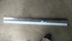
I had ordered another step drill bit to bore the holes out to fit the rubber bung of the lights...It was a 3/4"

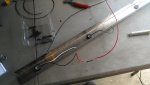
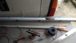
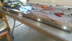
At first I had layed out and made pilot holes, the started to drill out to fit. The channel is stainless so its wierd.. My drills ended up getting dull and stopped drilling altogether... So today( with the new bit) I finished up and drilled out, and used a dremel tool to finish off the size. Got all the lights installed and figured out how to layout a harness for each bank...

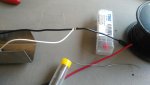
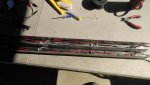
I decided to run the bus power wires and just split the insulation open to splice into the line, and solder/shrink connections after, for each. Also I zapstraped the length together, to tidy it up and make it look like a proper harness... ( I did do a test on both before the shrink)
I missed my motor winding days.. could have used some of that tie string we used for tying up the motor endrings. Would have been pretty sharp looking.

Now left, I have to mount them to the canopy, make a short harness for the light switch and wire up a power line from the engine compartment fuse block.

The Main task and hassle is done....
 

Attachments

  • IMG_20200601_152410.jpg
    IMG_20200601_152410.jpg
    186.3 KB · Views: 1
  • IMG_20200601_145037.jpg
    IMG_20200601_145037.jpg
    225.1 KB · Views: 1
  • IMG_20200601_145024.jpg
    IMG_20200601_145024.jpg
    216.9 KB · Views: 1
  • IMG_20200530_134545.jpg
    IMG_20200530_134545.jpg
    220.3 KB · Views: 0
  • IMG_20200530_125928.jpg
    IMG_20200530_125928.jpg
    320.2 KB · Views: 1
  • IMG_20200601_153215.jpg
    IMG_20200601_153215.jpg
    208.3 KB · Views: 1
  • IMG_20200601_165257.jpg
    IMG_20200601_165257.jpg
    230 KB · Views: 1

mckutzy

Well-known member
Messages
8,353
Reaction score
109
Location
bc, canada
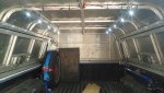
The other day I did the final install of the light bars...

I mounted to the roof structure using straps(I wasnt paying too much attention when I was thinking before and thought I had more ribs to screw into, but didnt so I just strapped it up anyways....).

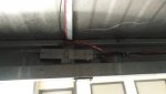
Joined the pairs together with wago clips, ran the power underneath the truck bed, up through the hole I drilled in the bed with the other light power wires.
Mounted a switch up behind the light inside, easy to grab at and actuate.
They dont drop down too much and are out of the way. lights up pretty good, dont have to fiddle around with a darn phone or flashlight when messing about in the back of the truck looking for something.....
Overall Im pretty impressed with myself.. pretty clean install I think..

A buddy was saying I should make a master switch inline from the inside as to control when It comes on/off, as to not leave it on when I shut down the truck at night or any time away from it, as any time you would turn your lights off. Im still on the fence about that one.. but it wouldnt be all that hard to rout a line through a hole I already know from the last truck I had used...
 

Attachments

  • IMG_20200606_142434.jpg
    IMG_20200606_142434.jpg
    253.8 KB · Views: 0
  • IMG_20200606_142443.jpg
    IMG_20200606_142443.jpg
    147.5 KB · Views: 0
Top