even simpler...
test ONLY the switch, no battery (no chance to short circuit anything) no nothing..
attach either one of the probes to either of the terminals (just take notes)
and the other one to one of the two remaining..
go to continuity test mode.
no turn the switch (and take your notes)
1 & 2 [key pos 0,1,2]
1 & 3 [key pos 0,1,2]
2 & 3 [key pos 0,1,2]
Now in keypos 0 NONE should be connected internally [no beep whatsoever]
in keypos 1 you should hear a beeping sound of the multimeter (in continuity mode)
with exactly one pair (two) terminals (likely 1 & 2) but not in 1&3 or 2&3 (or whatever pair it happens to be)
and in the third key position you should find that all three terminals are in fact connected (beeps no matter what pair you pick to test)
Got that?
Nice.. now look at your diagram again.. see the connecting lines in the box (according to key position 0,1 and two starting from the bottom) ?
the horizontal lines marks the connected terminals.
all you have to do is follow your notes to find which one is which now

1&2 beep in key pos 1; but 2&3 do not, then 1 is red, 2 is black and 3 yellow/red
2&3 beep in key pos 1; but 1&3 do not, then 2 is red, 3 is black and 1 will be yellow/red
1&3 beep in key pos 1; but 1&2 do not, well 3 is red, 1 is black and 2 will be yellow/red
and the best part of it: if you swap red and black by accident nothing happens;
only check if any of the terminals are actually continuing to the switch case;
and if so (can only be one terminal) that MUST BE BLACK.
easy huh?
'sid
 IMG_20170414_221941459_HDR.jpg135.4 KB · Views: 2
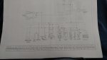 IMG_20170415_145010354.jpg152.8 KB · Views: 10
 IMG_20170415_145232607.jpg191.6 KB · Views: 3
