------- Notes -------
After seeing a lot of confusion about how to adjust governors (rather than removing them altogether) I decided to do a writeup on how they work.
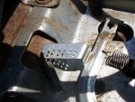
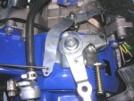
The picture of the throttle setup is from a Harbor Freight 2.5 HP engine (first photo). It's a very simple setup, and the general concept is rather commonly used.
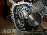
The crankcase picture is of a 6.5 HP Honda type (second photo, credit: AGK -- www.affordablegokarts.com. they have a good guide for governor removal of the 6.5)
The 2.5 is governed slightly differently than the 6.5, however, for the sake of this guide there is no gap.
Please note different engine have different governors which may look/act different, however the concept remains largely the same. In this guide I will refer to the arm connected directly to the carburetor as the governor arm, and the handle to control the speed (with governor in place) as the throttle arm. Also, in the picture of the throttle setup, the carburetor is attached to the rod running left off of the governor arm, and when that rod is pushed left the carburetor is opened.
------- The internals -------
Most small engines use centrifugal governors. Long story short, it's a little combination of parts in the engine that when it spins, it pushes in some direction, usually in line with the shaft of the gear. The faster it spins, the harder it pushes.
If you refer to the crankcase picture, the small gear in the top left is the centrifugal governor. The little arm on top of it which runs up and out of the engine block is connected to the governor arm in the throttle assembly. For this engine, the arm inside the crankcase will be pushed towards the camera, causing the governor arm on top of the block to be pushed counterclockwise, looking down from the top.
The governor arm pulling the carburetor closed harder with higher engine revs is shared nearly universally across all governed industrial engines.
------- The externals -------
Refer to the first picture for this section.
If you notice, the only connection between the throttle arm and the governor arm is a spring, whereas the governor arm is directly linked to the carburetor. This means that the governor arm position is the only thing which directly controls the throttle plate in the carburetor.
The throttle arm moves the governor arm solely by spring tension. More spring tension pulls the governor arm to the open throttle position harder.
In the throttle hookup image, when the engine is not running, it takes very little movement to fully open the throttle. After that, all the throttle arm does is increase the spring tension between it and the governor. (As a side note, some engines will actually spring the carburetor open very slightly - when the engine is running this is negligible, however when the engine is stopped this opens the throttle, and can create easier starts)
What this does while the engine is running, in essence, is when you increase the throttle substantially it will completely open the throttle. While the engine is speeding up due to this, the centrifugal governor will start to push harder and harder against the governor arm.
Eventually this force and the spring tension between the throttle arm and the governer arm will be equal. If the engine were to increase in speed, the governor arm would overpower the spring tension and close the throttle more (slowing down the engine), whereas if it decreased in speed, the governor would lose power and the spring would pull the carburetor further open. Esentially, how hard you pull on the governer arm directly correlates to the governed RPMs of the engine.
------- How to adjust it -------
If you haven't gotten it already, if you pull harder on the governor arm, the engine revs higher. There are a few ways to do this. The most common is backing out the throttle arm stop screw. If you look at the first picture, you can see that the screw is backed all the way out. This allows the throttle arm to travel farther, and the farther you stretch a spring, the more force it pulls with.
The second method is repositioning the spring between the throttle arm and governor arm. In the picture, you can see the governor arm has three holes in it already for the spring. If you were to move the spring inwards, it would pull on a point closer to the pivot of the governor arm, meaning less torque on the governor arm per the same pulling force. It's possible to do the same on the throttle arm itself, but on a different principle. Instead of putting more or less torque on the governor arm, moving the spring on the throttle arm primarily effects the amount of travel on the end of the spring (and hence how far you stretch it).
The third method is swapping the springs. The logic behind this is rather straightforward, however you will typically want to have a rather accurate method of measuring the spring force.
After seeing a lot of confusion about how to adjust governors (rather than removing them altogether) I decided to do a writeup on how they work.
The picture of the throttle setup is from a Harbor Freight 2.5 HP engine (first photo). It's a very simple setup, and the general concept is rather commonly used.
The crankcase picture is of a 6.5 HP Honda type (second photo, credit: AGK -- www.affordablegokarts.com. they have a good guide for governor removal of the 6.5)
The 2.5 is governed slightly differently than the 6.5, however, for the sake of this guide there is no gap.
Please note different engine have different governors which may look/act different, however the concept remains largely the same. In this guide I will refer to the arm connected directly to the carburetor as the governor arm, and the handle to control the speed (with governor in place) as the throttle arm. Also, in the picture of the throttle setup, the carburetor is attached to the rod running left off of the governor arm, and when that rod is pushed left the carburetor is opened.
------- The internals -------
Most small engines use centrifugal governors. Long story short, it's a little combination of parts in the engine that when it spins, it pushes in some direction, usually in line with the shaft of the gear. The faster it spins, the harder it pushes.
If you refer to the crankcase picture, the small gear in the top left is the centrifugal governor. The little arm on top of it which runs up and out of the engine block is connected to the governor arm in the throttle assembly. For this engine, the arm inside the crankcase will be pushed towards the camera, causing the governor arm on top of the block to be pushed counterclockwise, looking down from the top.
The governor arm pulling the carburetor closed harder with higher engine revs is shared nearly universally across all governed industrial engines.
------- The externals -------
Refer to the first picture for this section.
If you notice, the only connection between the throttle arm and the governor arm is a spring, whereas the governor arm is directly linked to the carburetor. This means that the governor arm position is the only thing which directly controls the throttle plate in the carburetor.
The throttle arm moves the governor arm solely by spring tension. More spring tension pulls the governor arm to the open throttle position harder.
In the throttle hookup image, when the engine is not running, it takes very little movement to fully open the throttle. After that, all the throttle arm does is increase the spring tension between it and the governor. (As a side note, some engines will actually spring the carburetor open very slightly - when the engine is running this is negligible, however when the engine is stopped this opens the throttle, and can create easier starts)
What this does while the engine is running, in essence, is when you increase the throttle substantially it will completely open the throttle. While the engine is speeding up due to this, the centrifugal governor will start to push harder and harder against the governor arm.
Eventually this force and the spring tension between the throttle arm and the governer arm will be equal. If the engine were to increase in speed, the governor arm would overpower the spring tension and close the throttle more (slowing down the engine), whereas if it decreased in speed, the governor would lose power and the spring would pull the carburetor further open. Esentially, how hard you pull on the governer arm directly correlates to the governed RPMs of the engine.
------- How to adjust it -------
If you haven't gotten it already, if you pull harder on the governor arm, the engine revs higher. There are a few ways to do this. The most common is backing out the throttle arm stop screw. If you look at the first picture, you can see that the screw is backed all the way out. This allows the throttle arm to travel farther, and the farther you stretch a spring, the more force it pulls with.
The second method is repositioning the spring between the throttle arm and governor arm. In the picture, you can see the governor arm has three holes in it already for the spring. If you were to move the spring inwards, it would pull on a point closer to the pivot of the governor arm, meaning less torque on the governor arm per the same pulling force. It's possible to do the same on the throttle arm itself, but on a different principle. Instead of putting more or less torque on the governor arm, moving the spring on the throttle arm primarily effects the amount of travel on the end of the spring (and hence how far you stretch it).
The third method is swapping the springs. The logic behind this is rather straightforward, however you will typically want to have a rather accurate method of measuring the spring force.
Attachments
-
 DSCN1296.jpg115.1 KB · Views: 24
 -
 gov-removal-3.jpg20.7 KB · Views: 29