Hemi Predator Build #2

Status
Not open for further replies.

Kleyny

New member
Messages
140
Reaction score
4
Location
Brisbane Australia
You know I'm not happy when I'm looking at my dremel attachments wondering if I could successfully notch the piston for valve relief.

---------- Post added at 01:07 AM ---------- Previous post was at 01:06 AM ----------

This guy makes it seem easy.
https://www.youtube.com/watch?v=Jpk2pKASjBE

That's a cool video. I'd give it a shot if I needed to after watching this video. What's the worst that could happen :p
 

bob58o

SuckSqueezeBangBlow
Messages
9,646
Reaction score
1,851
Location
Chicago-town USA
Somebody on another forum PM'd me with a link to a thread on a third forum.

This talks about how the 6" driven pulley on a 30 series TC prevented this guy from Revving high. He says the 7" Pulley with 1:1 ratio allowed him to rev higher. Hmmmm?
I've heard about people not being able to rev high with TC's but figured it was from belt slip. He says the Overdrive acts as the limiter. But not sure it really makes sense to me. Is it the overdrive? Or is it the original gear ratio and lack of power higher up in that RPM range that prevents the engine from revving higher???????

Interesting stuff here.

https://www.oldminibikes.com/forum/...9464-adjusting-comet-tav2-engagement-rpm.html
 

KartFab

Active member
Messages
3,381
Reaction score
57
Location
Dallas, TX
here is my personal experience:

30 series with the briggs 5hp flathead tops out at 4300 rpm. thats with the 8t jackshaft and stock rear axle sprocket and what 19" tires on the baja heat.

I have also been told that it is the gearing that makes it top out at those lower rpms, not so much the torque converter itself.

I was speaking with another guy who had his torque converters top out at 5500 rpm. He hadn't advanced his timing though, so that may have been holding him back.

With so many variables, and so little information out there, my opinion is that you might want to get the biggest rear axle sprocket and smallest jackshaft sprocket for the best chance of hitting those higher rpms.


What happened with joes mini bike build? IIRC he had some issues with his engine not making RPMs and it was related to timing... then adjusted it and stilll only got 5750 rpm max on a 44 magnum drive/40driven.

I personally top out at 5500 rpm with the 40 series, but that is with the cam that tops out at 5500 rpm.


Im thinking that if your engine target max rpm is up to snuff with all the mods, and your gearing is right, that you can hit that rpm. Just some thoughts and conjecture though, no actual proof.
 

bob58o

SuckSqueezeBangBlow
Messages
9,646
Reaction score
1,851
Location
Chicago-town USA
here is my personal experience:

30 series with the briggs 5hp flathead tops out at 4300 rpm. thats with the 8t jackshaft and stock rear axle sprocket and what 19" tires on the baja heat.

I have also been told that it is the gearing that makes it top out at those lower rpms, not so much the torque converter itself.

I was speaking with another guy who had his torque converters top out at 5500 rpm. He hadn't advanced his timing though, so that may have been holding him back.

With so many variables, and so little information out there, my opinion is that you might want to get the biggest rear axle sprocket and smallest jackshaft sprocket for the best chance of hitting those higher rpms.


What happened with joes mini bike build? IIRC he had some issues with his engine not making RPMs and it was related to timing... then adjusted it and stilll only got 5750 rpm max on a 44 magnum drive/40driven.

I personally top out at 5500 rpm with the 40 series, but that is with the cam that tops out at 5500 rpm.


Im thinking that if your engine target max rpm is up to snuff with all the mods, and your gearing is right, that you can hit that rpm. Just some thoughts and conjecture though, no actual proof.

I think I agree. I feel like it would be the gear ratio, weight, tire size that limits RPMs.

My old 30 series handled 7000 RPM at the crankshaft.

That was with 13"tires, 10T TC Sprocket, 54T Rear Sprocket.
So with 0.9:1 Overdrive, I was at 4.86:1.

It just makes sense to me that the OD changes the gear ratio so that will also change max RPM.

6:1 with 1:1 from the 7" TC driven is still 6:1.
6:1 with 0.9:1 from the 6" TC driven is now 5.4:1.

10% change in gear ratio to me makes sense that you may see a 10% decrease in max RPM????

Just like if my cam should be good to 7000 RPM and I'm runnig 5:1 and only hitting 6000 RPM, I would expect switching to 6:1 would increase my max RPM.

I guess I will play around and find out.

But first I got to notch this piston.
 

bob58o

SuckSqueezeBangBlow
Messages
9,646
Reaction score
1,851
Location
Chicago-town USA
So for a valve relief pocket there should be 0.050" radial clearance.
So the pocket should have a diameter = Valve size +0.100"
28.5mm = 1.122"

1.122 +0.100 = 1.222"

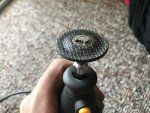
Dremel has a kit that has a 1.5" grinding wheel and a series of 1.25" sanding dics (60gr, 120gr, 240gr). I think I can make this work.

I broke the EZ attachment mandrel trying to make the 1.5" grinding disc a 1.25" grinding disc. Going to see if I can return it. I may have been at like 35k RPM and I think it may only be rated for 20k?

---------- Post added at 01:49 PM ---------- Previous post was at 01:47 PM ----------

Id like to order a 32mm valve and make a cutting tool like in the video. but I guess I'll give this a try.
 

bob58o

SuckSqueezeBangBlow
Messages
9,646
Reaction score
1,851
Location
Chicago-town USA
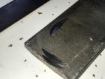
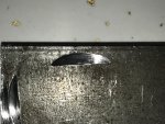
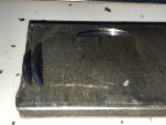
Here are some practice cuts.
The grinding wheel is now 1.25".
Looks like this can be done right?
I don't think I need much more than this type of little notch.
Going to use clay once more, then use the clay impression to mark the piston. The clay will also give me a better idea as to what angle I should come in at. Then I guess Ill remove the piston from the block and see if I work up the courage to try this today.
 

Attachments

  • IMG_0949.jpg
    IMG_0949.jpg
    255.5 KB · Views: 3
  • IMG_0950.jpg
    IMG_0950.jpg
    381.5 KB · Views: 2
  • IMG_0951.jpg
    IMG_0951.jpg
    211.7 KB · Views: 3
  • image.jpg
    image.jpg
    281.5 KB · Views: 2

Noseoil

Terrible Tim
Messages
57
Reaction score
5
Location
Tucson
Do you have a drill press & vise? You can use the to hold things at the right angle & run the notch a little at a time that way, just sayin...
 

bob58o

SuckSqueezeBangBlow
Messages
9,646
Reaction score
1,851
Location
Chicago-town USA
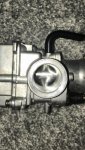
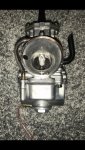
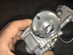
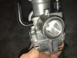
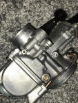
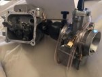
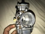
China carb!
24mm PWK
 

Attachments

  • IMG_0963.jpg
    IMG_0963.jpg
    145.4 KB · Views: 2
  • IMG_0962.jpg
    IMG_0962.jpg
    159.8 KB · Views: 3
  • IMG_0961.jpg
    IMG_0961.jpg
    225.5 KB · Views: 3
  • IMG_0960.jpg
    IMG_0960.jpg
    177 KB · Views: 3
  • IMG_0958.jpg
    IMG_0958.jpg
    361.9 KB · Views: 3

bob58o

SuckSqueezeBangBlow
Messages
9,646
Reaction score
1,851
Location
Chicago-town USA
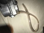
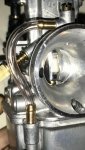
So what is the purpose of this tube?

Comes from the float bowl. Routed back into the air filter side of the carb with an adjustment screw??? There is another vent/overfill spout with a tube at the bottom of the bowl. I get that tube... I think. But this tube (in the pic) is confusing me.
 

Attachments

  • carb hoses.jpg
    carb hoses.jpg
    229.7 KB · Views: 5

bob58o

SuckSqueezeBangBlow
Messages
9,646
Reaction score
1,851
Location
Chicago-town USA
Trying to figure out this carb, but photobucket has ruined everything. How am I supposed to see what these guys are talking about when all I get is this on every other site. Making DIY that much more difficult. At least here people were steered away from photobucket.

I think that is the Power Jet????
 

Attachments

  • pb.jpg
    pb.jpg
    116.6 KB · Views: 1

bob58o

SuckSqueezeBangBlow
Messages
9,646
Reaction score
1,851
Location
Chicago-town USA
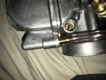
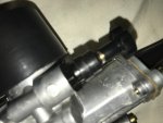
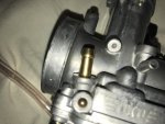
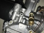
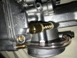
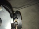
Fuel inlet -pic 1
Choke Plunger -pic 2
Air Screw -pic 3
Bowl Overfill drain? -pic 4
Bowl Vent? -pic 5
Idle Speed Adjustment (8th pic, also in 6)


This other hole- pic 6- (opposite what I think is the bowl vent and next to the idle speed adjustment) I believe is not drilled through. This carb seems to be made so everything could have gone on either side.

It looks like one more blank hole - pic 9- next to the choke plunger on the engine side of the Venturi that's not drilled.

I think I have most of it figured out. Just leaves these last ports - pic 8- which are already tubed together.

Power Jet Circuit??
EDIT: So I guess it is the power jet circuit and supposedly it is of poor quality and could just be kept closed. I think the Power Jet and non power jet carbs sell for the same price.
 

Attachments

  • IMG_0974.jpg
    IMG_0974.jpg
    213.5 KB · Views: 1
  • IMG_0973.jpg
    IMG_0973.jpg
    249.9 KB · Views: 1
  • IMG_0972.jpg
    IMG_0972.jpg
    206.3 KB · Views: 1
  • IMG_0970.jpg
    IMG_0970.jpg
    203.3 KB · Views: 1
  • IMG_0969.jpg
    IMG_0969.jpg
    198.3 KB · Views: 1
  • IMG_0976.jpg
    IMG_0976.jpg
    224.3 KB · Views: 1
  • IMG_0977.jpg
    IMG_0977.jpg
    135.2 KB · Views: 1
  • IMG_0971.jpg
    IMG_0971.jpg
    229.9 KB · Views: 0
  • IMG_0978.jpg
    IMG_0978.jpg
    180.7 KB · Views: 0

bob58o

SuckSqueezeBangBlow
Messages
9,646
Reaction score
1,851
Location
Chicago-town USA
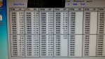
So looking at Barry Young's FB page, he dynos the same engine before and after porting the head. It was a AKRA legal stocker.
13.04 Max HP at 5750 RPM before the port.
13.58 Max HP at 5750 RPM after.

Unported is 11.98 HP at 4500 RPM.
Ported is is 8.56 HP at 4500 RPM

At 6750 RPM Ported is 12.47 HP.
Unported is 11.31 HP at 6750

Both ported an unported are at 12.77 HP at 5050 RPM.

So It seems that the porting hurts HP below 5050 RPM, at least according to the info here. Makes sense I suppose. Just like a big carb will hurt low end.

Surprised that the peak HP RPM didn't change. It stayed at 5750 RPM before and after.
 

Attachments

  • port 2.jpg
    port 2.jpg
    88 KB · Views: 3
  • port 3.jpg
    port 3.jpg
    87.4 KB · Views: 2

Denny

Canned Monster
Messages
11,827
Reaction score
8,284
Location
Mayberry, Indiana
Bowl vent is from top of bowl to top of air horn. the line on the bottom of bowl is to drain the float bowl before servicing or for long term storage.


Denny
 

bob58o

SuckSqueezeBangBlow
Messages
9,646
Reaction score
1,851
Location
Chicago-town USA
Bowl vent is from top of bowl to top of air horn. the line on the bottom of bowl is to drain the float bowl before servicing or for long term storage.


Denny

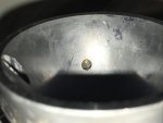
So I believe the tube on the bottom of the bowl is connected to the straw looking thing. It sticks up higher than the float level, so it would have to be an overfill fuel drain right?

The other tube sticking up from the top of the bowl I believe is connected to the small port seen near the bottom of the bowl. I believe when the signal inside the air horn is strong enough it's supposed to pull fuel from the bottom of the bowl and spray it into the carb through this jet.
 

Attachments

  • IMG_0980.jpg
    IMG_0980.jpg
    246.8 KB · Views: 1
  • IMG_0979.jpg
    IMG_0979.jpg
    142.2 KB · Views: 1
  • IMG_0989.jpg
    IMG_0989.jpg
    83.4 KB · Views: 0
  • IMG_0988.jpg
    IMG_0988.jpg
    89.2 KB · Views: 0
  • IMG_0987.jpg
    IMG_0987.jpg
    218.5 KB · Views: 0

bob58o

SuckSqueezeBangBlow
Messages
9,646
Reaction score
1,851
Location
Chicago-town USA
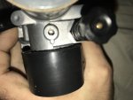
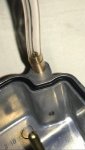
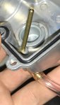
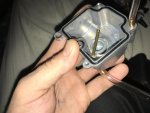
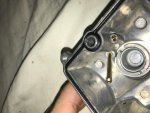
There is also this tube on the top half of the carb. It gets inserted into this well in the bowl and looks like it goes to this hole on the engine side of the slide.
Looks like tiny jet fills the well from the bowl and the tube pulls the fuel up and squirts it into the intake. Or atmospheric pressure pushes the fuel into the intake, what ever is clever.

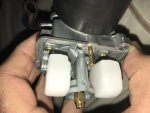
Last pic shows the low and main jets.
 

Attachments

  • IMG_0990.jpg
    IMG_0990.jpg
    199 KB · Views: 2
  • IMG_0991.jpg
    IMG_0991.jpg
    244.8 KB · Views: 2
  • IMG_0992.jpg
    IMG_0992.jpg
    137.9 KB · Views: 1
  • IMG_0983.jpg
    IMG_0983.jpg
    240.7 KB · Views: 3
Status
Not open for further replies.
Top