Help with controller

Status
Not open for further replies.

ceny

New member
Messages
2
Reaction score
0
Hi,
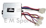
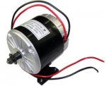
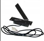
Can anyone please help me? I'm new to both gokarts and electric ones. Ive welded my frame and it holds up well (not bad for a newbie). I have a 24V, 350w motor and a small controller to match. Ive wired the motor to the power output from the controller and the batteries to the power input to the controller. I have a foot pedal that I have plugged into the lead called 'de-railer' and nothing happens when i press it. The controller also has plugs for:Hi,


Ignition
Indicator
Brake
Charge Port
Brake Light

I'm thinking it has something to do with the Ignition switch, so i tried joining the two wires together. This resulted in the motor turning over full throttle with the foot pedal having no control. So i separated the wires again.
What am i missing? Any help welcome.

Thanks

Paul
 

itsid

Moderator
Staff member
Messages
11,563
Reaction score
247
Location
Ruhrpott [Germany]
:useless: 'nearly' I'm afraid.

But I'll try anyways, to give you a head start :D

The Derailleur should have three leads (what colors do you have?)

pick your multimeter and measure DC between the outer pins.
you should have a 5V reading.
got that? perfect.

Not?, forgot to turn on the controller perhaps?
(join the wires again ;))
still nothing?
well then I'm afraid you need to test as long as you find the 5V..
(two more tests.. center + left, center + right)

Note down which pair gives you 5V, and which one is +5 and which is GND
(if your read -5V on your multimeter, the black probe touches +5V;
if you read 5V the red probe touches +5V ;))
Mark the two accordingly.
and you can also mark the center lead as Signal.

Perfect,

Now what kind of throttle do you have? (potentiometer or hall effect)

if it's potentiometer style, it's a simple test to find out.
Set your multimeter to Resistance (Ohm)
and read between two pins( say the outer pins for starters again)
you should read nearly 0 Ohms (maybe 2-5 Ohms... not much at least)
Now, fully depress the throttle and read again (it should climb up to 10k Ohms or more)

got that too? (if not swap until you do)
perfect.

You can mark the center line (the untouched;)) of the throttle as "Signal"
Now put the black probe on the signal line (center?) of the throttle and retest.
Any changes between idle and full throttle? then the red probe is +5V
if not it's GND

For a HE throttle refer to the manual which lead has to be connected to +5, to signal and to Ground..
if you cannot find a spec sheet for it;
find the two leads that have ~10k Ohms 'at idle'
mark the remaining lead as +5;
now without powering it up, it'll be difficult to find out which of the other ones is GND and which is Signal.
if one of them is black, it should be GND though.
so try that first and connect (if the motor isn't turning at full throttle, swap the two)
while you're at it.. mark the leads ;)

great you now have marked +5, signal and GND on the throttle
and the controller.

pair them up! (5 to 5, gnd to gnd, signal to signal)

Your motor should now turn according to throttle position..

if it doesn't..

We need PICS!!!
and whenever possible model number of motor, throttle and most of all... controller!

'sid
 

ceny

New member
Messages
2
Reaction score
0
Help with controller update

Hi sid,

Thank you very much for replying to my post. Sorry its been some time since an update.
As I don't have a multimeter, I was about to go and buy one but decided to have another look at the wires. I moved the wires around on the throttle foot pedal (they were not matching colour wise) so that they did match (black with black/ red with red) and it now works! looks like the plug was put on backwards in China.

I can now move ahead with the rest of the build. Thank you once again and in future I will post pictures.

Paul

Picture of throttle, controller and motor attached.
 

Attachments

  • 24v 350w controller.jpg
    24v 350w controller.jpg
    50 KB · Views: 2
  • 24v 350w motor.jpg
    24v 350w motor.jpg
    24 KB · Views: 3
  • Metal-Hall-effect-Scooter-foot-throttle-pedal-Accelerator.jpg
    Metal-Hall-effect-Scooter-foot-throttle-pedal-Accelerator.jpg
    91.6 KB · Views: 2

armsoffury

New member
Messages
1
Reaction score
0
Same problem

Now that your issue is resolved this post will be of no use to you but I figured I would reply anyways. I have the same exact setup as you do except for I have a 48v 1000w 3000 rpm motor. I also had the same exact issue as you. My controller looks identical to yours except it is the controller for the 48v engine. Anways, after a few hours of troubleshooting with my multimeter I ended up switching the red and blue wire on my throttle control and it worked. I contacted the company I bought my parts from and they said they have been receiving several similar complaints. So your problem is quite common I guess.
 
Status
Not open for further replies.
Top