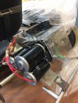
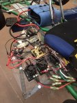
In 2014 I built a small vehicle for a school project. It was powered by 2 robotics (CIM) motors and a custom made water-jet gearbox. It used an 18Ah 12V SLA battery and produced about 1hp. It also used a joystick to control the forwards, backwards, tank-steering movements. It was a lot of fun but I never really had reason to keep it around; plus it was so slow.
In 2015, I decided to build a go-kart using a scrap frame I had purchased from school. Making a 4-stroke go-kart seemed pretty cool but I was never really motivated to put in all the work. I do love cars, driving, racing and all that, but I was hoping I could make something more exciting and worthwhile. I decided that I would scrap the robot vehicle (which had many problems of its own, especially with the gearbox) and add the robotics components to my gas powered kart for a little torque boost. My inspiration included the 2014 F1 cars, McLaren P1, La Ferrari, and the Porsche 918.
This project has taken almost 3 years and is still not entirely complete. I may submit it for the 2017 build-off but at the moment I will just make a journal for it as a lot of work has already been done.
I am aware it would be faster if I used a bigger engine. It would be more economical to have no electric component. It would accelerate better with a torque converter. But these are not the reasons I am building this. I find all of the hybrid-technology out there these days super cool and I want to see if I could develop my own hybrid-concept. So this is the story of the Green eXperiment.
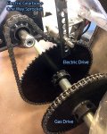
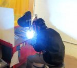
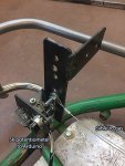
Here are some pictures of the original electric robotic vehicle:


10/07/2014
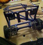
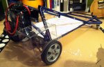
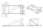
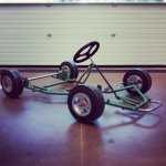
I sourced out a frame from a local technology institution, it was $120 and includes the frame, four 6” wheels and tires (two tubes need replacing) it has a nice steering wheel and shaft already installed. Someone else has already installed some custom spindle brackets and spindles. I’ll be fabricating everything else from scratch. This was a good deal.

12/14/2015
With the frame sitting and gathering dust for over a year I’ve decided to build the vehicle powered by a typical 4-stroke engine. I want electrical motors to assist in acceleration between 0-7kph and then we want the motors to turn off at speeds higher.
To avoid killing the CIM motors I should program a ball shifter transmission to shift out of gear after 7kph before turning off the motors. The first gear would be 20:1? 30:1? to the wheels and then the second gear would be 5:1 or 4:1 engaged after the vehicle is already in motion. Drive wheels are 11.5" diameter, if geared at 5:1 we’re looking at ~35-40kph.
If both electric and gas motor are engaged, the CIM motors will get toasted by the much stronger gas motor (unintentionally spinning at 12000RPM. The CIMs freely spin @ 5000RPM. Another issue that might occur is that the CIM motor will slow the vehicle down by providing resistance as it is geared much higher (unintentional alternator)
I’ve created a document with the outlined inputs and outputs I’m trying to configure. This is only for the electric portion.
I'm looking at the 3 CIM ball shifter on VEXpro, we have a few hundred dollars to play with.
1/26/2016
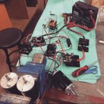
Pulled apart all the robotics components from the previous robot build. This build used an Arduino, 2 motor controllers, 2 CIM motors, 2 40A breakers, a PlayStation joystick, 12V 18 Ah SLA battery, 120A breaker.
The robot with one person on board was capable of 10kph theoretical top speed… I think we really only hit 8kph in testing though. It was really peppy with all that torque, the weight of the vehicle was only ~240lb with the driver. The new kart was 325lb with the driver.

2/2/2016
I added a Victor SP motor controller (already have 2 Victor 888s) to complete the 3 CIM gearbox, with the extra CIM the kart should produce ~1.5hp
For some reason the new controller keeps spinning the motor at idle and will not stop. The old Victor 888 does not spin under the same code. I have moved cables around between the two models but the Victor SP still keeps spinning during idle.
FIXED 04/2016: Finally fixed this issue after 2 months, the new Victor SP uses pulse lengths of 0.5ms to 2.4ms. I added this line to the code for the Victor SP to remap the output to motor:
I’ve also decided to stop being lazy and officially started using proper wire connectors instead of just soldering stuff together. This actually turned out to be easier.
More to come...
In 2015, I decided to build a go-kart using a scrap frame I had purchased from school. Making a 4-stroke go-kart seemed pretty cool but I was never really motivated to put in all the work. I do love cars, driving, racing and all that, but I was hoping I could make something more exciting and worthwhile. I decided that I would scrap the robot vehicle (which had many problems of its own, especially with the gearbox) and add the robotics components to my gas powered kart for a little torque boost. My inspiration included the 2014 F1 cars, McLaren P1, La Ferrari, and the Porsche 918.
This project has taken almost 3 years and is still not entirely complete. I may submit it for the 2017 build-off but at the moment I will just make a journal for it as a lot of work has already been done.
I am aware it would be faster if I used a bigger engine. It would be more economical to have no electric component. It would accelerate better with a torque converter. But these are not the reasons I am building this. I find all of the hybrid-technology out there these days super cool and I want to see if I could develop my own hybrid-concept. So this is the story of the Green eXperiment.
Here are some pictures of the original electric robotic vehicle:
10/07/2014
I sourced out a frame from a local technology institution, it was $120 and includes the frame, four 6” wheels and tires (two tubes need replacing) it has a nice steering wheel and shaft already installed. Someone else has already installed some custom spindle brackets and spindles. I’ll be fabricating everything else from scratch. This was a good deal.
12/14/2015
With the frame sitting and gathering dust for over a year I’ve decided to build the vehicle powered by a typical 4-stroke engine. I want electrical motors to assist in acceleration between 0-7kph and then we want the motors to turn off at speeds higher.
To avoid killing the CIM motors I should program a ball shifter transmission to shift out of gear after 7kph before turning off the motors. The first gear would be 20:1? 30:1? to the wheels and then the second gear would be 5:1 or 4:1 engaged after the vehicle is already in motion. Drive wheels are 11.5" diameter, if geared at 5:1 we’re looking at ~35-40kph.
If both electric and gas motor are engaged, the CIM motors will get toasted by the much stronger gas motor (unintentionally spinning at 12000RPM. The CIMs freely spin @ 5000RPM. Another issue that might occur is that the CIM motor will slow the vehicle down by providing resistance as it is geared much higher (unintentional alternator)
I’ve created a document with the outlined inputs and outputs I’m trying to configure. This is only for the electric portion.
I'm looking at the 3 CIM ball shifter on VEXpro, we have a few hundred dollars to play with.
Computer
Arduino
Inputs
Pedal with potentiometer
Speed sensor
Output
Gas motor position
CIM motors (victor motor controllers)
Ball shifter transmission 2-3 CIM motors
Gas motor position
No throttle
Full throttle
Transmission position
P1 = acceleration mode (gear reduction)
P2 = coasting mode (free gear, disconnected from CIM motors)
CIM motor mode
Throttle control (P1,<7 km/h )
Disconnect (P2, >7 km/h)
Control
INPUT Potentiometer = ON (voltage TBD)
AND Speed Sensor = < 7 kph
OUTPUT gas power = FULL
OUTPUT cim motors = FULL
OUTPUT trans position 1 (acceleration mode)
INPUT Potentiometer = ON
AND Speed Sensor = > 7 kph
OUTPUT gas power = FULL
OUTPUT cim motors = FULL
OUTPUT trans position 2 (coast mode)
INPUT Potentiometer = ON
AND Speed Sensor = > 8 kph
OUTPUT gas power = FULL
OUTPUT cim motors = OFF
OUTPUT trans position 2 (coast mode)
INPUT Potentiometer = OFF
OUTPUT gas power = OFF
OUTPUT cim motors = OFF
OUTPUT trans position 1 (acceleration mode)
1/26/2016
Pulled apart all the robotics components from the previous robot build. This build used an Arduino, 2 motor controllers, 2 CIM motors, 2 40A breakers, a PlayStation joystick, 12V 18 Ah SLA battery, 120A breaker.
The robot with one person on board was capable of 10kph theoretical top speed… I think we really only hit 8kph in testing though. It was really peppy with all that torque, the weight of the vehicle was only ~240lb with the driver. The new kart was 325lb with the driver.
2/2/2016
I added a Victor SP motor controller (already have 2 Victor 888s) to complete the 3 CIM gearbox, with the extra CIM the kart should produce ~1.5hp
For some reason the new controller keeps spinning the motor at idle and will not stop. The old Victor 888 does not spin under the same code. I have moved cables around between the two models but the Victor SP still keeps spinning during idle.
FIXED 04/2016: Finally fixed this issue after 2 months, the new Victor SP uses pulse lengths of 0.5ms to 2.4ms. I added this line to the code for the Victor SP to remap the output to motor:
servo.attach(pin, 1000,2000);
I’ve also decided to stop being lazy and officially started using proper wire connectors instead of just soldering stuff together. This actually turned out to be easier.
More to come...
Attachments
-
 LOG01.jpg156 KB · Views: 205
 -
 LOG02.jpg143.3 KB · Views: 204
 -
 LOG03.jpg110.7 KB · Views: 203
 -
 LOG04.jpg69.9 KB · Views: 202
 -
 LOG05.jpg61.4 KB · Views: 203
 -
 LOG06.jpg142.4 KB · Views: 204