Greg's Go-Kart Project part 1 frame

Status
Not open for further replies.

GregMartin

I like fast cars
Messages
117
Reaction score
0
Location
Brisbane Australia
Greg's Go-Kart Project

Greg’s Go-Kart Project​
Introduction
I created this document to provide some detail on the process I went through to build a go-kart from scratch for my boys.
My Workshop
Before I go into the detail of the go-kart build I’ll quickly describe my workshop and the tools I have available to make this project possible. Firstly the most important machine is an arc welder, mine is a single phase unit good for about 140Amps.
My arc welder.jpg
I also have a small gas-less MIG welder pictured below that I used to weld the sheet metal.
mig.jpg
I have a very old lathe which is surprisingly accurate if you are prepared to be patent when setting up the job in the four jaw independent chuck, aligning the tail stock, setting the combination slide etc.
My shed 3.jpg
My shed 2.jpg
My shed 1.jpg
It makes things a lot easier if you have benches, vices, a drill press, bench grinder etc.

Materials
• RHS mild steel square section 25mm x 25mm x2.5mm (thickness)
• Mild steel flat bar 40mm x 5mm
• Mild steel flat bar 20mm x 5mm
• Mild steel round bar 20mm
• Mild steel round bar 10mm
• Mild steel round bar 6mm
• Mild steel tube 26.9mm (OD) x 2.3mm (thickness)
• Mild steel plate 200mm x 150mm x 5mm
• Sheet metal from old office furniture

British Standard Whitworth
I was fortunate enough to have a fairly complete set of Whitworth taps and dies as well as a set of Whitworth spanners. I found fabricating parts using Whitworth threads simplifies the process. I purchased some boxes of 3/8” and ½” nuts and bolts of various lengths. Whitworth sizes refer to the bolt diameter and not the across the flats of the hexagon bolt head. This frustrates some people as the opening on the spanner is much larger than the size stamped on it. However it makes it easy, if you want to put a thread on a 3/8” rod you simply use a Whitworth 3/8” die. You can then thread a standard Whitworth nut onto it using a British Standard Whitworth 3/8” spanner.

Frame
I created a frame using RHS steel square section 25mm x 25mm x 2.5mm. This is relatively easy to arc weld and it is strong. Initially I used an old Modern Mechanics go-kart frame plan which is widely available on the internet to get a rough idea of dimensions and general configuration. After I worked out the dimensions I cut the steel and welded it together on the concrete floor so that I had a flat surface. I used magnetic right angle clamps pictured below to keep the frame square and it all turned out pretty well.
welding-clamp.jpg
framing-1.gif
This diagram is very detailed. It is way more complicated than it needs to be however it gives an idea of what’s required. Below is a drawing showing the dimensions of the frame that I welded up. All dimensions are in millimetres.
kart frame.jpg
Frame with steering brackets.jpg
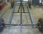
In this picture you can see the engine mounting plate, the brackets for the steering spindles and the housing for the steering column. I used a triangle configuration to hold the steering column rather than a single upright. I used the triangle arrangement because if the kids had a crash it might hurt a bit but it wouldn’t ruin there future.
 

Attachments

  • Frame with steering and rear axle 2.jpg
    Frame with steering and rear axle 2.jpg
    46.4 KB · Views: 36

GregMartin

I like fast cars
Messages
117
Reaction score
0
Location
Brisbane Australia
Greg's Go-Kart Project part 2 Steering

Steering
Working out the steering is one of the most challenging parts of the project. I turned up the steering spindles on my lathe so that they matched the steering brackets perfectly. The brackets were manufactured out of 40mm x 5mm flat bar. I welded 20mm x 5mm flat bar to the front of the spindles to attach to the tie rods and I welded ¾” Whitworth bolts to the spindles to be used as the stub axels. The spindles are held in place by ½” Whitworth bolts i.e. king pins. I also fitted grease nipples to the spindles to allow for easy maintenance. I built some linkages out of flat bar to perform the same function as a universal joint. The principal being that the linkage allows the spindle bar to move in the horizontal plane and the tie rod end to moves in the vertical plane. The tie rods are constructed out of 10mm rod with 20mm x 5mm flat bar used to fabricate the tie rod ends. One end is threaded to take a 3/8” Whitworth nut. There are some more linkages incorporating 20mm x 5mm flat bar and a 3/8” Whitworth nut. This arrangement allows for adjustment to perform a wheel alignment. The pitman arm is also made of 20mm x 5mm flat bar and the steering column is 10mm rod. This has been adequate however in hindsight a larger diameter steering column may be a slightly better option. I turned up aluminium bushings to locate the steering column in the housing which is 26.9mm tube. I also fitted grease nipples top and bottom to keep the steering bushings lubricated. I choose to use Whitworth nuts, bolts and threads for the reasons mentioned previously. For all steering components I purchased castle nuts and drilled the bolts to allow for split pins.
Frame with steering and rear axle 2.jpg
Frame with bumper bar and seat.jpg
Above you can see the steering components are all assembled and a bumper-bar has been added to protect the steering. I ended up shortening the pitman arm as the steering was too direct. It should be about 180 Degrees lock-to-lock.
spindles.jpg
Above is a picture of commercially available steering spindles. This is an alternative to making them yourself.
Tie rod end and brake pedal.jpg
Above is a close up of my homemade tie rod end universal joint. You probably don’t need to go to this amount of trouble however this steering assembly has absolutely no play or wobble. So it worked out very well.
az1841-13.jpg
az8140.jpg
Likewise tie rods, tie rod ends, steering shafts and pitman arms are all commercially available if you would prefer to purchase rather than manufacture.
Pitman arm and tie rod adjustment.jpg
 

GregMartin

I like fast cars
Messages
117
Reaction score
0
Location
Brisbane Australia
Greg's Go-Kart Project part 3 Engine

The Engine
Initially I used a Briggs and Stratton 3.5HP horizontal shaft engine with a 5/8” shaft pictured below
3dot5HP Briggs.jpg
The engine was always a little down on power. I tried a couple of things. First I removed the governor this had the desired effect. Then I drilled out the baffles on the standard muffler unfortunately this just reduced the engines backpressure and it made less power. Next I manufactured a header pipe for the engine this definitely improved the power output. To manufacture the header I sawed off the threaded end of a standard muffler. The inside diameter is about ½” and the outside is about ¾”. I then welded a 14” length out 26.9mm tube to the threaded muffler end. The effect is that the exhaust gases exit through the standard ½” exhaust port which then opens up to ¾” for 14” which seems to be pretty close to a tuned length.
Below are some photos of the engine after painting with the header pipe and Max Torque centrifugal clutch fitted.
3dot5HP briggs with pipe and paint 1.jpg
3dot5HP briggs with pipe and paint 2.jpg
Home made power pipe for briggs.jpg
This engine was ok for a while however it was still under powered. I looked at ways of increasing power, but in the end I decided to replace the engine with a 6.5HP Honda clone.
Honda Clone.jpg
I got this engine for AU $137. You can get them cheaper in the U.S. however postage to Australia is quite expensive for something this size. Once I received this engine I opened the crankcase and removed the governor components. I left the pin in place that the governor is located on because to take it out would require the removal of the flywheel etc. And I would the have to block the hole with a bolt anyway. Likewise I left the lever that attaches to the throttle linkage as I will be using it in my throttle linkage arrangement. I also left the low oil sensor in place as I am not fitting a billet crank or rod there is no need to remove it. I did however disconnect it on the outside of the engine and remove the relay that connects it to the shutoff switch and coil contacts.
I made a throttle linkage by using most of the parts that came with the engine. The throttle plate is made up of a fixed base plate and a moving plate held in place with a nylock lock nut. I made a nylon bush to allow the moving plate to move smoothly and evenly. I replace the throttle governor actuating spring with a solid rod and fitted return springs. I then made up some cable retention hardware for both the fixed on moving portions of the throttle plate. On the moving plate the cable is retained by a small bolt with a hole drilled in it and nuts fitted to hold the cable secure. On the fixed portion I had a plastic cable sheath retainer off an old whipper-snipper which I modified and strengthened with a steel bracket.
Throttle Linkage 1.jpg
Throttle Linkage 2.jpg
I have done most of the standard modifications that people do with these engines. I purchase an open header pipe, a K&N style air filter, an air filter adaptor, GX140 emulsion tube and a main jet drilled to .036”. When I had the crankcase open I noticed that the camshaft was a nylon type so I decided not to upgrade the valve springs from 10lb to 18lb as is generally recommended. Also I have not replaced the flywheel so I don’t really want the engine to rev over about 5000rpm. This engine makes plenty of power low in the rev range.
Clone mods 1.jpg
Clone mods 2.jpg
 

GregMartin

I like fast cars
Messages
117
Reaction score
0
Location
Brisbane Australia
Greg's Go-Kart Project part 4 Drive Train

Drive Train
When gathering parts for this go-kart build I managed to get the wheels, rear axle with sprocket and chain from an old Cox Scout ride on mower. The chain is either a #40 or #41. The sprocket has 48 teeth so I purchased a 10 teeth #41 Max Torque Centrifugal Clutch. This gearing works well with the 6.5HP Honda Clone however it was probably a bit tall for the Briggs 3.5HP engine which also ran a 10 tooth clutch. The rear axle was too narrow so I cut it and lengthened it by slipping each end into a piece of 1” gas pipe and welding it up. To weld it I set it up in a couple of V blocks and took my time. The results are a straight axle (amazing). The axle is suspended under the frame by bearing hangers.
Frame with steering and rear axle 1.jpg
The above picture shows the lengthened axle with sprocket attached to the frame by bearing hangers.
Vblocks.jpg
I used a couple of V blocks similar to this to hold the axle in place while I welded it.
 

GregMartin

I like fast cars
Messages
117
Reaction score
0
Location
Brisbane Australia
Greg's Go-Kart Project part 5 Brakes

Brakes
I purchase a disk and a calliper on-line and then worked out an arrangement that would work. I made a bracket for the calliper that allows it to slide laterally allowing it to self centre as the disk pads wear. I made up a linkage to actuate the brake calliper from the pedal using rods and pivot points which I turned up and fitted with grease nipples.
BrakeDisk_and_calliper.jpg
The above picture shows the brake disk and calliper with calliper mounting arrangement. It also shows part of the brake linkage with pivot point and grease nipple.
disk brake.jpg
calliper.jpg
Pictured above are the brake components I purchased from MFG Supply. They are a 6 3/8” disk with a 1” bore and the brake calliper is a Go-Kart and Mini-Bike Disk Brake Assembly
Brakes only slow you down.jpg
After paint 2.jpg
Above pictures show more detail of the brake linkage arrangement

Pedals
These are pretty straight forward. The brake pedal activates a rod which applies the brake via a linkage arrangement. The accelerator pedal operates the throttle via a cable. Both have a return spring attached to the frame.
Tie rod end and brake pedal.jpg
Above is the brake pedal
loud pedal.jpg
Above is the accelerator pedal with cable retainer and return spring visible.
 

landuse

Moderator
Staff member
Messages
18,626
Reaction score
224
Location
Pietermaritzburg, South Africa
When I had the crankcase open I noticed that the camshaft was a nylon type so I decided not to upgrade the valve springs from 10lb to 18lb as is generally recommended. Also I have not replaced the flywheel so I don’t really want the engine to rev over about 5000rpm.

Drive Train
When gathering parts for this go-kart build I managed to get the wheels, rear axle with sprocket and chain from an old Cox Scout ride on mower. The chain is either a #40 or #41. The sprocket has 48 teeth so I purchased a 10 teeth #41 Max Torque Centrifugal Clutch. This gearing works well with the 6.5HP Honda Clone however it was probably a bit tall for the Briggs 3.5HP engine which also ran a 10 tooth clutch.

Welcome to the forum Greg, it looks like you have all the skills needed for a build like this.

Have you actually finished the kart? Does it ride well. I am surprised you say the gear ratio you have now (4.8:1) works well. That is one tall ratio you have. You will probably be MUCH happier with a 60T sprocket. No lies.

Just a note, when you upgrade your valve springs to 18lb, you need to replace your rod and flywheel with billet steel. The harder springs prevent valve flutter and if your rod isn't replaced, you can have serious damage

Oh, and well done!!
 

OzFab

New member
Messages
15,615
Reaction score
8
Location
Warwick Qld, Australia
Nice job :thumbsup:

The only thing I would've done different (apart from the aforementioned gearing) was use lighter guage tubing. Having said that, how does it go?

R.I.P Brocky
 

Blazkowiez

Kart Aficionado
Messages
2,538
Reaction score
2
Location
Houston, Texas
I love the build you've done here. My question regards the clutch on the motor, how do you intend to oil the clutch every 2 hours of use? That chain guard while very impressive looks slightly restrictive to me unless there is a service hole I don't see.
 

GregMartin

I like fast cars
Messages
117
Reaction score
0
Location
Brisbane Australia
Welcome to the forum Greg, it looks like you have all the skills needed for a build like this.

Have you actually finished the kart? Does it ride well. I am surprised you say the gear ratio you have now (4.8:1) works well. That is one tall ratio you have. You will probably be MUCH happier with a 60T sprocket. No lies.

Just a note, when you upgrade your valve springs to 18lb, you need to replace your rod and flywheel with billet steel. The harder springs prevent valve flutter and if your rod isn't replaced, you can have serious damage

Oh, and well done!!
Thanks very much landuse
I acutely finished this cart a couple of years ago. At that time it had the 3.5HP Briggs. And your right the gearing was too tall. The kids were still able to get up to speed pretty easily but I struggled on grass, I could get it going on bitumen though. Also when I first built it the pitman arm was too long and it only has about 60Deg lock-to-lock. The kids complained that it was very direct and they were right. I rolled it, more like flipped it. And of course after that I shortened the pitman arm.

Anyway I only recently upgraded the engine and with the new 6.5HP Honda clone it has heaps of torque down low. It spins the wheels on takeoff (on grass ) and likewise you can perform some pretty impressive doughnuts. It can theoretically do about 40mph at 5000rpm but I haven’t measured it yet.

With regard to the engine mods it’s a slippery slope. New valve springs, new cam, new rod, new flywheel, then what? New carby new head etc. etc. I built it for the kids to muck around on and it’s already frighteningly fast
 

GregMartin

I like fast cars
Messages
117
Reaction score
0
Location
Brisbane Australia
Nice job :thumbsup:

The only thing I would've done different (apart from the aforementioned gearing) was use lighter guage tubing. Having said that, how does it go?

R.I.P Brocky
Hey thanks Fabroman
Originally I was going to use 25mm x 25mm x 1.6mm but the guy at the steel suppler suggested something thicker and I’m glad he did. It was easy to weld and you know you’ve got plenty of penetration.
 

jman231994

New member
Messages
724
Reaction score
0
Location
Australia
Love the build, the amount of detail you gave will probably help some new people trying to work out how to do their own kart.......Is it strange that I'm most envious of your tap and die set? hahaha
 

GregMartin

I like fast cars
Messages
117
Reaction score
0
Location
Brisbane Australia
Oh Yeah
My Grandfather was a fitter and turner and I ended up with at lot of his stuff, including his lathe. You can see some of his stuff in my workshop pictures and that’s where the Whitworth taps and dies came from. I did a trade as an electrical fitter/mechanic and had to buy a set of Whitworth spanners to work on old English transformers and switchgear
 

OzFab

New member
Messages
15,615
Reaction score
8
Location
Warwick Qld, Australia
I saw that & thought it was an awesome trubute to the king of the mountain. Not exactly like Brocky's but probably something to do with technical legalities
 

newrider3

New member
Messages
1,674
Reaction score
0
Location
Colorado
Excellent build, very well thought out and documented.
Though I can say I've never heard of someone purposefully putting Whitworth hardware back on a project. :D
 
Status
Not open for further replies.
Top