Giant RC Car Build Thread

Status
Not open for further replies.

Troikos

New member
Messages
26
Reaction score
0
Location
Brandon, MB, CA
Hello all! This will be the build thread for my RC car that I'm working on. I threw together a quick sketch-up of the idea and hope you guys have some feedback. This is the second version of this car that I'm building from scratch with all new and redesigned electronics.

The tires I got for it seemed a little big when I saw them in person but are quickly growing on me. I can switch them back to 6" rims later if its warranted. The plans as they stand right now call for a 28" wheel track and 36" wheel base. This was a quick sketch-up that I did to see how the drive system would all fit together. Any feedback is appreciated.

Engine is a Honda GC160 with a TC mounted to it (not in the sketch because I couldn't find one pre-made)

Animated (4.33MB in size)


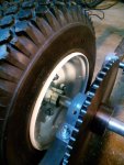
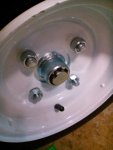
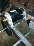
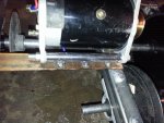
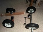
I already have a few of the parts in now.
2014-02-09 16.36.40.jpg2014-02-09 16.36.48.jpg

Axel is too long and will need to be cut down. Going to be building it out of 1.5" square tubing. Any idea how thick I should go to balance strength and weight for something like this? I'm still not sure what the best way to mount the front spindles would be without lowering the front of the frame. I'd like to keep it level if at all possible. While this wont be getting much air time, I'd like it to be able to take a decent hit and I'm not sure if the spindles will stay on if they were mounted like in the animation. Would gussets be enough to keep them in place? My other concern is that the center of gravity will be too high with that narrow of a wheel base.

[Edit] Just realized the sprockets on my jack shaft were backwards. :/
 
Last edited:

OzFab

Well-known member
Messages
15,615
Reaction score
70
Location
Warwick Qld, Australia
Wow, this shoud be interesting :popcorn:

The plans as they stand right now call for a 28" wheel base and 36" long from the wheel centers.

FYI: Wheelbase is the distance between the front & rear axles, centre to centre; track is the distance between wheels on the same axle, again, centre to centre; so, armed with that new information, which of your measurements is which?

I'm still not sure what the best way to mount the front spindles would be without lowering the front of the frame. I'd like to keep it level if at all possible.

There's a number of ways to achieve that, depending on the design:

You could mount a C bracket to the frame & mount the spindles to them or

You can have a bolt protruding through the bottom of the frame to which you can mount the spindles...

My other concern is that the center of gravity will be too high with that narrow of a wheel base.

If you're concerned about COG, mount the engine lower; weld a plate on the lower edge of the frame & use it as the engine mount
 

Troikos

New member
Messages
26
Reaction score
0
Location
Brandon, MB, CA
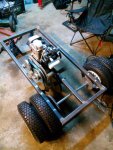
Sorry for the lack of updates. I didn't die. :) This weekend was the first time this year that its been bearable to be outside. Got the main frame cut and welded. Somehow the frame developed a twist which took a good hour or two along with a few cut welds to get out. I'm sure it was something that I did as this is my first time building anything. Also got the main ribs cut and tacked in place. The neighbors kid wanted to get some practice welding so he's been my helper for the day doing all the welding.
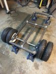
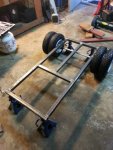
Decided to go with dualies in the back which might get swapped out with single extra wide tires later on. The width of the car along with the width of the extra tires ended up having a quarter of an inch of space left on the axle, purely by luck.

The place where I'm getting the steel has been out of angle iron in the size I need but are supposed to have it in by Tuesday. With that, I can get the secondary ribs in place to hold the other side of the gas motor, the electric motor and the steering servo. In the interest of saving material and weight, I decided not to run the center tube right to the front.

Shopping list for tomorrow include shaft collars and drive sprockets. Once I size those out, I can mount the jack shaft and disc brake.

2014-03-09 19.48.24.jpg

2014-03-09 19.48.36.jpg
 

fowler

New member
Messages
5,463
Reaction score
18
Location
Bullsbrook West Aus
this s going to be epic

just a side thought

with no diff
u may want to mount stuff as far forward as u can to get weight over the steerers
 

Troikos

New member
Messages
26
Reaction score
0
Location
Brandon, MB, CA
I have a 120AH deep cycle battery planned for near the front. That should give plenty of weight for steering. It might get swapped out with something smaller down the road if it turns out to be too heavy.

Still no angle iron. :(

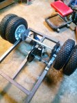
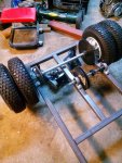
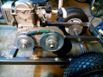
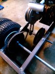
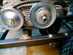
Mounted the jack shaft. Welded the sprocket and pulley. I tried to find a sprocket hub that would fit on the electric motor but no such luck right now. I'm thinking that a belt drive for the electric motor is a better plan for now anyway so that if something stops the wheels, the belt will slip rather than stall the motor. I still don't know what the stall current for the motor is and until I am able to run tests and find it, I think its better to stay on the safe side.

Got all of the keys cut and the wheels and drive sprocket mounted. The rest need to wait until I figure out placement of the brake caliper and motors.

Note that the frame is upside down in all of these pictures.

2014-03-12 21.26.31.jpg

2014-03-12 21.26.16.jpg

2014-03-12 21.25.36.jpg

2014-03-12 21.26.00.jpg
 

Troikos

New member
Messages
26
Reaction score
0
Location
Brandon, MB, CA
Well, I thought I had managed a good day's work yesterday but noticed that when I flipped the frame over, I had put the jack shaft and drive sprocket on the wrong side. :mad2:

So after getting those swapped around and getting my angle iron today. I mounted the engine, secured the sprockets and ran the chain. Everything is just tacked in place for now.

I still cant figure out the best way to mount the brake caliper and still be able to control it using a linear actuator.

I'm going to pick up some flat stock tomorrow and see if that will be an acceptable way to mount the electric motor instead of angle iron. The bracket that the electric motor will pivot on should add more than enough strength to the flat iron.

The brackets for the steering servo will get installed tomorrow and then I will have to figure out the best way to mount the spindles. The arms that come off them are welded on at an angle which I would assume would be to match the angle that the steering column meets the frame. I'm not sure how this will effect my setup with the steering servo coming strait down from the frame. Any suggestions on this?

2014-03-13 22.59.58.jpg

2014-03-13 23.00.13.jpg

2014-03-13 23.00.31.jpg

2014-03-13 23.00.55.jpg
 

fowler

New member
Messages
5,463
Reaction score
18
Location
Bullsbrook West Aus
Throw up some pics

There should be a few angles in your spindles

Where it mounts to the frame it should be leaning in a bit
That's the kingpin
And it sets the kpi and camber

The arm that will actuate the spindle will also be pointing in a bit
This is te steering arm and it sets Ackerman
And helps with keeping the wheels in track while cornering

If u draw a line along the steering arm and keep drawing it back
The two lines from each side should intresect somewhere over or behind the centre of the rear axle

Lastly the kingpin may lean back at the top
This sets the caster

And is to helps to keep the wheels pointed straight ahead


Throw up some pics

But when the steering spindles are all attracted
The spindle it's self should be perpendicular to the ground

And ao should the steering arm
 

OzFab

Well-known member
Messages
15,615
Reaction score
70
Location
Warwick Qld, Australia
I still cant figure out the best way to mount the brake caliper and still be able to control it using a linear actuator.

It will need to be a strong acuator to provide the required force to actuate the brake...

I'm going to pick up some flat stock tomorrow and see if that will be an acceptable way to mount the electric motor instead of angle iron. The bracket that the electric motor will pivot on should add more than enough strength to the flat iron.

1/8" angle is stronger than 1/4" flat stock of the same width, due, mostly, to the angle itself; each flat section of the angle may kink slightly but, it will take a lot of force to bend the overall length whereas I bent my own 1.25" x 1/4" spindle brackets using nothing more than a simple, home made bender...
 

Troikos

New member
Messages
26
Reaction score
0
Location
Brandon, MB, CA
The actuator that will be hooked to the brakes is able to push 110lbs of force. We will see if thats enough.

I was able to get the electric motor mounted today. Placed a piece of flat steel across the frame and mounted the pivot bracket to it. Had to weld some nuts to the bottom of the bracket to elevate it off the frame so that the motor mounts wouldn't hit. Works excellent. Now I just need to size a belt and make the piece that bolts to the last mount on the motor to hold it in place.

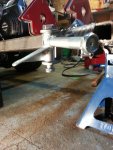
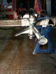
I've attached some photos of the front steering setup. I might need to elevate the servo as its hanging a little low right now. Yes, duct tape is a suitable kart making material. :)

I'd like your opinion of the best way to mount the spindles. in the photos it is taped on with the arm coming down. I'm not sure which way is up on these. I might need to weld on a piece of tube behind it and lower the spindle on the frame. At its current point, the front wheels are higher than the back and would cause a downward slope in the vehicle. I haven't decided if thats a good thing yet. :)

2014-03-14 21.49.26.jpg

2014-03-14 21.49.41.jpg

2014-03-14 21.41.00.jpg

2014-03-14 21.40.16.jpg
 

Troikos

New member
Messages
26
Reaction score
0
Location
Brandon, MB, CA
Based on what I've read, a positive caster would be the pivot point intersecting the road ahead of the contact point which would mean I have those spindles on backwards. It should be flipped around and placed on the other side for it to be correct, right? From what I've read, a "massive amount of caster" is a bad thing, especially for me as it makes steering more difficult. Steering needs to be as easy as possible for the servo.

Basically, what does this mean for me? How much harder would steering be with the spindles as they are? Should I cut the arms off and do them at a different angle?
 

fowler

New member
Messages
5,463
Reaction score
18
Location
Bullsbrook West Aus
Yeah

Steering geometry is part handling part driver comfort

U don't wanna have to hold al your strength on the wheel to keep it going straight

But an electronic servo is going to hold the same force on the steering all the time
Although without these angles u will get quite a bit of feed back to the servo

If the servo is strong
I wouldn't worry about camber at all
As for castor
Maybe a little bit to keep a bit of load off the servo
And u must keep the Ackerman

If the servo is likely to suffer from feedback then u will have to have all the angles

But turning will load the servo more
 
Status
Not open for further replies.
Top