Gear ratios and other burning questions

MacLaddy

New member
Messages
16
Reaction score
9
Hey folks,

I'm working on upgrading a Manco go-kart with a live axle and torque converter. It already has a new Predator 212 installed, so we're optimistically capable of around 8 ft-lbs at 2,500 rpm. The current setup is smoking the centrifugal clutch and mostly not moving my fat old frame around, so it definitely needs an upgrade. I'm capable of handling the math, but I haven't found a good answer to a few questions:

1. Are all torque converters 1 to 1 at full speed? I've found 30, 40, or other series for sale, but I'm not clear on what this implies. Are 30 series 3 to 1 at the start and 1 to 1 at full speed?
2. Is there a standard "best practice" gear ratio I should look for? I'm more inclined to determine required torque at the wheels, but I don't really want to calculate what it takes to accelerate my mass up a hill.

I don't have any numbers to provide a start for calculation, other than I'm planning to install 16X8-7 tires on the back. This will mostly be for my kids, so I don't want a crazy top speed.

Let me know what you think. I appreciate any input.

Thanks,
Mac
 

Denny

Canned Monster
Messages
10,900
Reaction score
7,201
Location
Mayberry, Indiana
10/60 or 6:1 60 tooth on axle and 10 tooth on the CVT.

The 30 series was originally designed for mini bikes. It uses an asymmetrical belt.

The 20 and 40 series CVTs were designed for gokarts and use a symmetrical belt. The 20 series is for engines with a 3/4” pto shaft. The 40 series is for engines with a 1” pto shaft. The belts are not interchangeable between the 2 series.
To learn more about the differences go to Go Kart Supply’s website under CVTs and read up about them.
 

bob58o

SuckSqueezeBangBlow
Messages
9,659
Reaction score
1,731
Location
Chicago-town USA
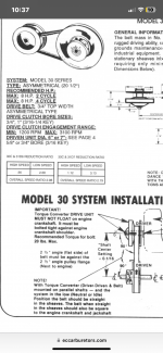
“ 1.
Are all torque converters 1 to 1 at full speed?

No, The standard 30 series is 0.9 : 1 fully shifted out.

I've found 30, 40, or other series for sale, but I'm not clear on what this implies.


Are 30 series 3 to 1 at the start and 1 to 1 at full speed?

2.68 : 1 in low and 0.9 : 1 in high when using a 6” driven unit.

3.13 : 1 in low and 1.12 : 1 in high when using a 7” driven unit


IMG_7283.png
 

MacLaddy

New member
Messages
16
Reaction score
9
10/60 or 6:1 60 tooth on axle and 10 tooth on the CVT.

The 30 series was originally designed for mini bikes. It uses an asymmetrical belt.

The 20 and 40 series CVTs were designed for gokarts and use a symmetrical belt. The 20 series is for engines with a 3/4” pto shaft. The 40 series is for engines with a 1” pto shaft. The belts are not interchangeable between the 2 series.
To learn more about the differences go to Go Kart Supply’s website under CVTs and read up about them.
Thanks. I've read up some from the Go Kart Supply website. What is the advantage/disadvantage to using an asymmetrical belt? I tried a quick google and YouTube search without luck. I'll probably dig into that question a little deeper.
 

MacLaddy

New member
Messages
16
Reaction score
9
“ 1.
Are all torque converters 1 to 1 at full speed?

No, The standard 30 series is 0.9 : 1 fully shifted out.

I've found 30, 40, or other series for sale, but I'm not clear on what this implies.


Are 30 series 3 to 1 at the start and 1 to 1 at full speed?

2.68 : 1 in low and 0.9 : 1 in high when using a 6” driven unit.

3.13 : 1 in low and 1.12 : 1 in high when using a 7” driven unit


View attachment 150015
Thanks. That's helpful and exactly what I was looking for. It appears to be close enough to 1:1 for a quick back of the napkin calculation, but there is clearly a difference in ratio.
 

MacLaddy

New member
Messages
16
Reaction score
9
So now that I know gear ratio, I am trying to track down a quality live rear axle kit and torque converter. In an effort to not break the bank, I've been looking through every option possible on eBay. Unfortunately, the sizes are wacky (at least for me) and their sprockets won't match any of the standard torque converters I can find. When I ask them for sprocket dimensions for replacement, I never get a good response.

This struggle took me to Go Power Sports. I found these two items that seem to fit everything I need, but they are much more expensive. The live axle kit seems cheaper than the eBay version, as that uses actual pillow block bearings and includes disc hydraulic brakes. The Go Power option has a cheesy bearing mount and a mechanical friction brake.

Thoughts on the best place to get this stuff? I also found that I can purchase the axle itself on Go Kart Supply, but I'm still trying to learn how the sprocket and brake disc mount to the axle. Do I need to specify a shoulder in the axle, or do they typically just have really long keyways?

1727394891250.png
 

Denny

Canned Monster
Messages
10,900
Reaction score
7,201
Location
Mayberry, Indiana
The 30 series is a little more inefficient and belts wear a little faster. The Jungle store (Amazon) CVTs are inexpensive and just as good and parts interchange with the Comet ones. Just do not use the cheap belts, they really suck! Only Use Genuine Comet Belts!!!
 

panchothedog

Well-known member
Messages
2,519
Reaction score
3,350
Post # 11 is telling you the truth. Kart supply shops ( all of them ) charge a few bucks more. They don't sell you junk. I can't say the same for E- bay or Amazon.
I have spent several thousand dollars over the past 5 years on kart and engine parts. Never been ripped off or received an inferior product from any of the larger legitimate kart supply shops. No comment on the prep H.
 

MacLaddy

New member
Messages
16
Reaction score
9
The cheap always comes out more expensive.
Save a little more and get the better quality stuff. It comes as a kit and will leave out all the guess work.

I hear Dennys got the strong stuff for that 🔥
Post # 11 is telling you the truth. Kart supply shops ( all of them ) charge a few bucks more. They don't sell you junk. I can't say the same for E- bay or Amazon.
I have spent several thousand dollars over the past 5 years on kart and engine parts. Never been ripped off or received an inferior product from any of the larger legitimate kart supply shops. No comment on the prep H.
Actually, they seem to be the same price, but don't get me wrong. I'm leaning towards the Kart sites. I don't like the idea of having non-standard sizes that I'm not able to match. Especially after I discovered that their chain sizes are incompatible with typical torque converters. Sounds like a constant expensive headache.

I don't like the wheels on Go Power Sports that are keyed instead of bolted. I've never had a go kart, but it seems like the key could easily shear. I've found bolted wheels on Gokartsupply.com (and OMB, but they're even more pricey) and building my own "kit" on there is more $$ but has the bolted wheels and hubs. I'm trying to piece together all the parts on their sites.

Should I even worry about this? Are keyed wheels perfectly fine for a 6 HP go kart?

So much to learn...
 

panchothedog

Well-known member
Messages
2,519
Reaction score
3,350
No you should not worry about that. Keyed wheels are fine. They will take a whole lot more than 6 horse power. At least double that. I'm sure that there are exceptions ( as I don't even pretend to know it all ) but many of the bolt on hubs are themselves keyed onto the axle. Buy with confidence. You aren't going to shear them.
 

BaconBitRacing

Well-known member
Messages
2,302
Reaction score
1,458
Location
N.C.
My wheels are bolted to the hubs which are keyed. That's how most karts came out of the factory. I get where you're coming from with that though, I've thought the same thing.
 

Master Hack

Well-known member
Messages
3,604
Reaction score
5,682
Location
Mountain top Labratory
No you should not worry about that. Keyed wheels are fine. They will take a whole lot more than 6 horse power.
This looks like sumpthin for Bob...

Transmitting torque with keyed shafts​

★ BY DANIELLE COLLINS 2 COMMENTS

FacebookXLinkedInShare
Power transmission between two rotating components requires a secure connection between the shaft of the driving component, and the hub of the mating part. One way to ensure torque transmission without slipping is by using a keyed connection. For most automation applications (motors, gearboxes, pulleys, etc.), a parallel key, also known as a straight key, with a square cross-section is used.
Keyed connections, however, do have a drawback—they require a reduction in shaft diameter of the torque-transmitting component. And of course, the smaller the diameter, the less torque can be transmitted before failure occurs. To demonstrate, below is an example of the maximum torque that can be transmitted by a keyless shaft, compared with the torque that can be transmitted by the same shaft when a key (per DIN 6885) is added.

Torque transmitted by a plain shaft​

Plain Shaft Torque
τ = yield stress; typically 50% of tensile strength; for this example, τ = 390 x 106 (N/m2)
J = polar moment of inertia (m4)

Polar Moment of Inertia
r = shaft radius (m)
For a solid steel shaft of 18mm diameter:
J = (3.1415 * (.009)4) / 2
J = 1.03 x 10⁻⁸ m4
T = (390 x 106 * 1.03 x 10-8 ) / .009
T = 446.6 Nm

Torque transmitted by a keyed shaft​

Keyed Shaft Torque
τ = yield stress; 390 x 106 for this example (N/m2)
d = shaft diameter (m)
l = keyway effective length (m)
h = keyway depth (m)

For a solid steel shaft of 18mm diameter, with keyway 6 wide x 32 long by 3.5 deep:
T = (390 x 106 * 0.018 * 0.032 * 0.0035) / 2
T = 393.1 Nm
In this case, the torque that can be transmitted when a key is added to the shaft is approximately 12 percent lower than the torque that can transmitted by the plain shaft (393 Nm vs 447 Nm). However, these calculations do not include any reduction factors to account for shock loads, reversing effects, or fatigue life—all of which can be a greater concern for keyed shafts than for plain shafts. Also, the above equations assume that the shaft will fail before the key. But there are two failure modes for parallel keys that must be considered: shear failure and compressive failure.

Shear Failure​

When the connection rotates, the shaft and hub (mating part) exert opposing forces on the key, attempting to shear the key. The maximum torque that can be transmitted before exceeding the yield strength of the key is calculated as:
Keyed Shaft Shear and Crush Torque
F = shear force acting on key (N)
Keyed Shaft Shear Force
r = shaft radius (m)
τ = yield stress; 390 x 106 for this example (N/m2)
w = key width (m)
l = keyway effective length (m)

F = 390 x 106 * 0.006 * .032
F = 74,880 N
T = 74,880 * .009
T = 673.9 Nm

Crushing Failure​

The second possible mode of failure, also caused by forces exerted on the key by the shaft and hub, is based on compressive forces, which can induce permanent deformation and crush the key. In this case, the maximum torque that can be transmitted is based on the height, rather than the width, of the key.
Keyed Shaft Shear and Crush Torque
F = compressive force acting on key (N)
Keyed Shaft Crushing Force
r = shaft radius (m)
τ = yield stress; 390 x 106 for this example (N/m2)
l = effective keyway length (m)
h = key height (m)

F = (390 x 106 * 0.032 * 0.006) / 2
F = 37,440 N
T = 37,440 * .009
T = 337.0 Nm
Based on the scenarios above, the limiting factor is actually the crushing force on the key, and the maximum torque that can be transmitted is reduced by approximately 25 percent (337 Nm based on crushing failure with a key versus 447 Nm for a plain shaft). Again, it’s important to note that the calculations for a keyed shaft do not take into account any service, application, or safety factors. So the recommended maximum torque may be lower than the examples above, depending on other application parameters.
Feature image credit: 4mechtech.com
 

bob58o

SuckSqueezeBangBlow
Messages
9,659
Reaction score
1,731
Location
Chicago-town USA
This looks like sumpthin for Bob...

Transmitting torque with keyed shafts​

★ BY DANIELLE COLLINS 2 COMMENTS

FacebookXLinkedInShare
Power transmission between two rotating components requires a secure connection between the shaft of the driving component, and the hub of the mating part. One way to ensure torque transmission without slipping is by using a keyed connection. For most automation applications (motors, gearboxes, pulleys, etc.), a parallel key, also known as a straight key, with a square cross-section is used.
Keyed connections, however, do have a drawback—they require a reduction in shaft diameter of the torque-transmitting component. And of course, the smaller the diameter, the less torque can be transmitted before failure occurs. To demonstrate, below is an example of the maximum torque that can be transmitted by a keyless shaft, compared with the torque that can be transmitted by the same shaft when a key (per DIN 6885) is added.

Torque transmitted by a plain shaft​

Plain Shaft Torque
τ = yield stress; typically 50% of tensile strength; for this example, τ = 390 x 106 (N/m2)
J = polar moment of inertia (m4)

Polar Moment of Inertia
r = shaft radius (m)
For a solid steel shaft of 18mm diameter:
J = (3.1415 * (.009)4) / 2
J = 1.03 x 10⁻⁸ m4
T = (390 x 106 * 1.03 x 10-8 ) / .009
T = 446.6 Nm

Torque transmitted by a keyed shaft​

Keyed Shaft Torque
τ = yield stress; 390 x 106 for this example (N/m2)
d = shaft diameter (m)
l = keyway effective length (m)
h = keyway depth (m)

For a solid steel shaft of 18mm diameter, with keyway 6 wide x 32 long by 3.5 deep:
T = (390 x 106 * 0.018 * 0.032 * 0.0035) / 2
T = 393.1 Nm
In this case, the torque that can be transmitted when a key is added to the shaft is approximately 12 percent lower than the torque that can transmitted by the plain shaft (393 Nm vs 447 Nm). However, these calculations do not include any reduction factors to account for shock loads, reversing effects, or fatigue life—all of which can be a greater concern for keyed shafts than for plain shafts. Also, the above equations assume that the shaft will fail before the key. But there are two failure modes for parallel keys that must be considered: shear failure and compressive failure.

Shear Failure​

When the connection rotates, the shaft and hub (mating part) exert opposing forces on the key, attempting to shear the key. The maximum torque that can be transmitted before exceeding the yield strength of the key is calculated as:
Keyed Shaft Shear and Crush Torque
F = shear force acting on key (N)
Keyed Shaft Shear Force
r = shaft radius (m)
τ = yield stress; 390 x 106 for this example (N/m2)
w = key width (m)
l = keyway effective length (m)

F = 390 x 106 * 0.006 * .032
F = 74,880 N
T = 74,880 * .009
T = 673.9 Nm

Crushing Failure​

The second possible mode of failure, also caused by forces exerted on the key by the shaft and hub, is based on compressive forces, which can induce permanent deformation and crush the key. In this case, the maximum torque that can be transmitted is based on the height, rather than the width, of the key.
Keyed Shaft Shear and Crush Torque
F = compressive force acting on key (N)
Keyed Shaft Crushing Force
r = shaft radius (m)
τ = yield stress; 390 x 106 for this example (N/m2)
l = effective keyway length (m)
h = key height (m)

F = (390 x 106 * 0.032 * 0.006) / 2
F = 37,440 N
T = 37,440 * .009
T = 337.0 Nm
Based on the scenarios above, the limiting factor is actually the crushing force on the key, and the maximum torque that can be transmitted is reduced by approximately 25 percent (337 Nm based on crushing failure with a key versus 447 Nm for a plain shaft). Again, it’s important to note that the calculations for a keyed shaft do not take into account any service, application, or safety factors. So the recommended maximum torque may be lower than the examples above, depending on other application parameters.
Feature image credit: 4mechtech.com
So it turns? Or what? lol
 

MacLaddy

New member
Messages
16
Reaction score
9
No you should not worry about that. Keyed wheels are fine. They will take a whole lot more than 6 horse power. At least double that. I'm sure that there are exceptions ( as I don't even pretend to know it all ) but many of the bolt on hubs are themselves keyed onto the axle. Buy with confidence. You aren't going to shear them.
My wheels are bolted to the hubs which are keyed. That's how most karts came out of the factory. I get where you're coming from with that though, I've thought the same thing.

You're both right, of course. I didn't even think about the fact that all torque is transmitted via the keyway. If anything, the wheel keys experience half the torque as the sprocket key. I was getting confused because some of the eBay axles I mentioned earlier connect the hub via splines. It really is too bad those sizes are so whacky, because they seem superior in many ways.
 

MacLaddy

New member
Messages
16
Reaction score
9
This looks like sumpthin for Bob...

Transmitting torque with keyed shafts​

★ BY DANIELLE COLLINS 2 COMMENTS

FacebookXLinkedInShare
Power transmission between two rotating components requires a secure connection between the shaft of the driving component, and the hub of the mating part. One way to ensure torque transmission without slipping is by using a keyed connection. For most automation applications (motors, gearboxes, pulleys, etc.), a parallel key, also known as a straight key, with a square cross-section is used.
Keyed connections, however, do have a drawback—they require a reduction in shaft diameter of the torque-transmitting component. And of course, the smaller the diameter, the less torque can be transmitted before failure occurs. To demonstrate, below is an example of the maximum torque that can be transmitted by a keyless shaft, compared with the torque that can be transmitted by the same shaft when a key (per DIN 6885) is added.

Torque transmitted by a plain shaft​

Plain Shaft Torque
τ = yield stress; typically 50% of tensile strength; for this example, τ = 390 x 106 (N/m2)
J = polar moment of inertia (m4)

Polar Moment of Inertia
r = shaft radius (m)
For a solid steel shaft of 18mm diameter:
J = (3.1415 * (.009)4) / 2
J = 1.03 x 10⁻⁸ m4
T = (390 x 106 * 1.03 x 10-8 ) / .009
T = 446.6 Nm

Torque transmitted by a keyed shaft​

Keyed Shaft Torque
τ = yield stress; 390 x 106 for this example (N/m2)
d = shaft diameter (m)
l = keyway effective length (m)
h = keyway depth (m)

For a solid steel shaft of 18mm diameter, with keyway 6 wide x 32 long by 3.5 deep:
T = (390 x 106 * 0.018 * 0.032 * 0.0035) / 2
T = 393.1 Nm
In this case, the torque that can be transmitted when a key is added to the shaft is approximately 12 percent lower than the torque that can transmitted by the plain shaft (393 Nm vs 447 Nm). However, these calculations do not include any reduction factors to account for shock loads, reversing effects, or fatigue life—all of which can be a greater concern for keyed shafts than for plain shafts. Also, the above equations assume that the shaft will fail before the key. But there are two failure modes for parallel keys that must be considered: shear failure and compressive failure.

Shear Failure​

When the connection rotates, the shaft and hub (mating part) exert opposing forces on the key, attempting to shear the key. The maximum torque that can be transmitted before exceeding the yield strength of the key is calculated as:
Keyed Shaft Shear and Crush Torque
F = shear force acting on key (N)
Keyed Shaft Shear Force
r = shaft radius (m)
τ = yield stress; 390 x 106 for this example (N/m2)
w = key width (m)
l = keyway effective length (m)

F = 390 x 106 * 0.006 * .032
F = 74,880 N
T = 74,880 * .009
T = 673.9 Nm

Crushing Failure​

The second possible mode of failure, also caused by forces exerted on the key by the shaft and hub, is based on compressive forces, which can induce permanent deformation and crush the key. In this case, the maximum torque that can be transmitted is based on the height, rather than the width, of the key.
Keyed Shaft Shear and Crush Torque
F = compressive force acting on key (N)
Keyed Shaft Crushing Force
r = shaft radius (m)
τ = yield stress; 390 x 106 for this example (N/m2)
l = effective keyway length (m)
h = key height (m)

F = (390 x 106 * 0.032 * 0.006) / 2
F = 37,440 N
T = 37,440 * .009
T = 337.0 Nm
Based on the scenarios above, the limiting factor is actually the crushing force on the key, and the maximum torque that can be transmitted is reduced by approximately 25 percent (337 Nm based on crushing failure with a key versus 447 Nm for a plain shaft). Again, it’s important to note that the calculations for a keyed shaft do not take into account any service, application, or safety factors. So the recommended maximum torque may be lower than the examples above, depending on other application parameters.
Feature image credit: 4mechtech.com
This takes me back a few years. Thanks for sharing. Using these numbers, the key needs about 250 lb-ft to experience a crushing failure. The Predator 212 can make about 8 lb-ft and with a 6:1 ratio we can achieve around 48 lb-ft.

It appears the key will survive... just barely. SF of 5.
 

panchothedog

Well-known member
Messages
2,519
Reaction score
3,350
FWIW. My very hottest built kart ( even though it's a 196cc engine) is built for maximum rpm. Probably around 12 or 13 hp at full song. The torque converter driven clutch is tuned ( light weights and heavy springs ) to engage at 4200 rpm, as high as I can get it with standard available parts. With one of my teenage granddaughters aboard ( about 110 lbs ) the thing will actually pop about a 2" wheelie when the throttle is mashed from a dead stop. This is with keyed rear wheels on asphalt on a Yerf-Dog kart that is 18 to 20 years old. No idea what the mathematical torque load is, but due to the high engagement rpm I'm certain that it's a lot more than just a smooth leanier take off.
 
Top