Front suspension design

Status
Not open for further replies.

randas

New member
Messages
7
Reaction score
0
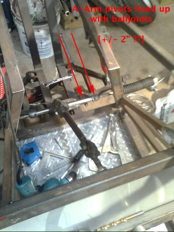
After literally years of working on it, I finally took my buggy out for its maiden voyage this past weekend. Not very impressed with the front suspension. In reverse it loads up the shocks. If I reduce the toe in it dose the opposite, loads up the shocks going forward. Also when I make a turn the side opposite to the direction I'm turning loads up. :censored: Don't get me wrong, It works, but not very happy with it. Any better designs?


theo

New member
Messages
872
Reaction score
1
The way you have the rack in relation to the a arms is giving you bump steer. You cant lower the rack so you have to raise the mounting of the a arms.
 

nomnom

New member
Messages
5
Reaction score
0
Location
CA
Not sure if this is the source of problems, but your scrub radius seems like it may be too large...combine this with what "theo" says above and it exacerbates the problem. Part of the reason that you saw it first in reverse could have to do with caster; caster that is good for forward movement is backwards for going in reverse...not saying you should change caster though.
 

fowler

New member
Messages
5,463
Reaction score
17
Location
Bullsbrook West Aus
yeah longer nd higher a arms
and gett a much smaller scrub radius

u should be able to draw a line though the a arm mounts and intersect the end on the rack

u should also be able to draw a line following your king pin and it should end up in the dead centre of your tire

also a bit more support on the a arms wouldnt go astray
 

fowler

New member
Messages
5,463
Reaction score
17
Location
Bullsbrook West Aus
ok this is how mine is set up i cant claim the design or the build as it was built from plans by someone who lost intrest and sold it to me as 1/2 a progect

the first pic shows the much smaller scrub radius and how the king pin angles in

the second shows how the rack should line up

the third shows how the a arm is not an issosolies triagle but a right angle
this allows the the tie rods to be striaghter

also the tie rod is at the same angle as the rear a arm bar, to be honest i can remeber why it had to be like this but i remeber it being the down fall on my last buggy

also note how these a arms are built from much less material but are stronger
lastly the rack in this is a little too wide but has no affect on bump steer with this much travel
 

Attachments

  • P1000096.jpg
    P1000096.jpg
    80.8 KB · Views: 29
  • P1000097.jpg
    P1000097.jpg
    63 KB · Views: 24
  • P1000098.jpg
    P1000098.jpg
    99.6 KB · Views: 31
  • P1000099.jpg
    P1000099.jpg
    107.9 KB · Views: 36

theo

New member
Messages
872
Reaction score
1
You can remove that nylon spacer on the spindle shaft to allow the hub and rim to move in closer to the kingpin. Also you can use a positive offset rim which will help you lots.
 

randas

New member
Messages
7
Reaction score
0
Ok, to sum up.

1) I should have the center of the A-arm pivot point centered with the center of the rack?

2) Longer a-arms. How much longer? Do I want the front track width the same as the rear? More? Right now its less.

iirc My caster is 15° right now. And my King pin is 10 or 15° but that changes with the suspension and it stays part compressed when driving.

What is the scrub radius?

u should be able to draw a line though the a arm mounts and intersect the end on the rack

By this you just mean the suspension pivot point should be center with the rack center?


I'll get some more pics up today of the whole machine to give you guys a better idea
 

fowler

New member
Messages
5,463
Reaction score
17
Location
Bullsbrook West Aus
no the a arm pivot needs to be centred with the ends of the rack

so where the tie rods come out of the rack (inside those rubber boots at each end)
u will have to take the rubber boot off to find the exact pivot point

as for length that is determined my size of vehical
mine has a front track of 1.2m and the overall wheel base is 2.4m

scrub radius
http://en.wikipedia.org/wiki/Scrub_radius
in thier pics they are useing a mcferson strut so the pic of the spring is where your king pin goes
 

theo

New member
Messages
872
Reaction score
1
With single a arms as long as the racks inner pivot joints are close to the a arm pivot up to 2" either side you will be ok. But you need the center line of the rack the same as the center of the a arm pivot point on the same line. Your R&P might be ok length wise, just try it.

It looks in the pic to me that you have no kpi on you front spindle, what you have is camber change, which is drastic with single a arms.

Remove that nylon spacer from the spindle and install your front tire and hub for us to look at.
 

Simon Thomas

New member
Messages
324
Reaction score
0
Location
Sarawak, Malaysia
Good Design

ok this is how mine is set up i cant claim the design or the build as it was built from plans by someone who lost intrest and sold it to me as 1/2 a progect

the first pic shows the much smaller scrub radius and how the king pin angles in

the second shows how the rack should line up

the third shows how the a arm is not an issosolies triagle but a right angle
this allows the the tie rods to be striaghter

also the tie rod is at the same angle as the rear a arm bar, to be honest i can remeber why it had to be like this but i remeber it being the down fall on my last buggy

also note how these a arms are built from much less material but are stronger
lastly the rack in this is a little too wide but has no affect on bump steer with this much travel

This is a good design especially on the front suspension:thumbsup:
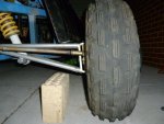
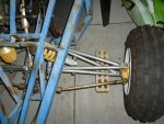
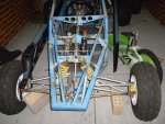
. Hope you can take more photos of it including the whole body frame and put them in your album for us to see it clearly. I have a dream to build something like this in future. Thanks.
 

randas

New member
Messages
7
Reaction score
0
Ok here we go, This part is for-sure correct?


Now this part. Needs to be changed or not? Going off my pictures as it stands I have a solid 2" maybe 3" Between the pivot points and the ball joint (the frame is 1.5" HSS)


Now scrub angle. I want 0 or what? Now that I think about it, your right, I have zero KPI. What I do have is camber [10° iirc] When I rebuild the front end should I have any camber or not?
I also have 15° or so caster. Good or?
I'm planning on getting different (bigger) tires/rims for the front. Guess I need to do that first.


With single a arms as long as the racks inner pivot joints are close to the a arm pivot up to 2" either side you will be ok. But you need the center line of the rack the same as the center of the a arm pivot point on the same line. Your R&P might be ok length wise, just try it.

It looks in the pic to me that you have no kpi on you front spindle, what you have is camber change, which is drastic with single a arms.

Remove that nylon spacer from the spindle and install your front tire and hub for us to look at.

I can do that this weekend. The machine is 160 miles away at the moment.


I posted some more pics of the whole machine in the gallery.

Thanks again guys :thumbsup:
 

theo

New member
Messages
872
Reaction score
1
That rack should be ok, if not make your a arm mounts out of 1 1/2" angle and you can lay them on top of your square tubes, doing this you can move your a arm pivot out to suit the rack length.
Get your rims and tires before you design in your kpi. KPI can intersect at the center of the tire up to 1" inwards. If you go inwards from the center you get more feel.
 
Status
Not open for further replies.
Top