Front End Problems

Status
Not open for further replies.

wagx2

New member
Messages
127
Reaction score
0
Location
Lexington NC
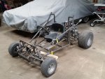
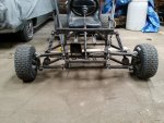
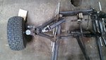
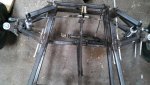
Not quite 3", but yes it is forward. The Karts frame is angled and instead of building a square box on the front of the kart for the front suspension I opted to just build the A arms on the angle of the frame. My thought process was I can keep the Kart shorter and lighter if I did this but after reading your post I probably shouldn't have. I have plans to reinforce the shock mounts as well as the rest of the Kart. Just haven't made it to that step yet. :thumbsup:

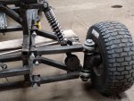
you would not have to extend the frame any longer, and it looks like you came in at a angle then sliced and put another angle in it, just at rear of a arms, so the box your referring to is already there, if you draw imaginary line and connect each mount of the a-arms four points on one side 4 points on the other side, that is the box of the front end, now if you shorten the shock mount and move it back to middle of the a arm points to line up with bottom shock mount I think you would like the over all look better than the tall mounts inline with front, first impression of your frame when you first posted it, I had a flash back of watching star wars when I was a kid, with luke skywalker sitting in the cockpit of a x-wing fighter, which was every kids bad, a@@ dream back then, with that shape I can picture the sides with panels and a nose cone which moving shock mount back will give you the room to make a nose piece to cover the box, your on the right track, the math and all the thoughts that get put in to the building process, it is very easy to get ahead of yourself, over think something only to run into another problem later in the build its your first build, and who cares what we think, EXCEPT for safety comments, your child want care if it drives sideways down the rd, cause they will be thinking I got the coolest (dad, uncle, neighbor,) in the the world the whole time......until you use it as punishment tool and ground them from it. nothing hurts as long as your having fun doing it.:thumbsup: may want to look at ebay, used set of a arms with spindles for golf carts and four wheelers are about the same price as 3/4 heim joints. and you get a product that has past geometry class, and is adjustable at the same time.

did you get more pics of what you said had changed, i'll check build thread.....
 

jasonH

New member
Messages
70
Reaction score
1
Location
Iowa
My shop is set up for wood so I am building the kart at my father in laws. He's 3 hours north of me and I didn't take any pictures of my failures this time. I did put in a call to have him snap a couple of the front end for me to show you.

EDIT**
Pics received. The long gold ball joints are just temporary. Didn't have the right size nuts laying around
 

Attachments

  • IMG95201503259517581295000.jpg
    IMG95201503259517581295000.jpg
    83.3 KB · Views: 19
  • IMG_20150325_175808_019.jpg
    IMG_20150325_175808_019.jpg
    75.6 KB · Views: 18
  • IMG_20150325_175815_824.jpg
    IMG_20150325_175815_824.jpg
    87.8 KB · Views: 15
  • IMG_20150325_175857_594.jpg
    IMG_20150325_175857_594.jpg
    88.9 KB · Views: 17

OzFab

Well-known member
Messages
15,615
Reaction score
65
Location
Warwick Qld, Australia
I found another possible problem, the steering arms on the hubs are very short, which equates to heave steering; I suggest you:

1. Switch the hubs, let to right, so the steering arms race rearward
2. Extend the steering arms taking ackermann into account
3. Move/redesign the pitman arm on the steering column

Even with those alterations, you may still have a degree of "bump steer" because the tie rods don't travel in the same line as the A arms...
 

wagx2

New member
Messages
127
Reaction score
0
Location
Lexington NC
the long bolts holding a arms on did you run it without nuts on them or are they a tight fit and hammered in? the angle pieces used as the mounts for a arms next time mount them with the leg against the frame to the out side that way you can get them as close to the a arm as possible to prevent arm from sliding front to back in the mount. if shocks are turned up right that will give you some clearance from a arm, and since the arms are not parallel to the ground during suspension travel, when they are coming up, they extend farther out than the tie rod will go so as it passes the reach of the rods both wheels will turn inward to adjust to the stretch that is not there. so set-up may need to adjust tie rods with toe out more than normal, mine the tie rods run on back side of spindle so set it up toe in more at rest, and that shock has a little adjustment turning the spanner nut you can make it stiffer which will help take some of the travel arch, out of the a arms, but means rougher ride, so there's a give and take situation you will have to address and decide which way you want it, stiff steering or stiff ride.
a arm.jpg

above may help explain, with a arms angle down you can see the vertical reference line, spindle plumb and straight, but as the riders weight is added, spring starts to compress arm starts upward travel hitting bumps and such at any speed sends arm farther up in its travel, once the travel breaks the vertical line the tie rod will not give so in your case the spindle will start to turn to allow the difference in the tie rod length, in your case wheels will start to be turned inward and will bind steering, worse in cornering because one arm will travel faster implying this pressure. so when you adjust the tie rods play with above comment, and also set it up with a rider with estimated weight sitting in it so that it will allow you set it up with the best possible measurement with maybe 1/4'' toe out instead of starting with 1/2'' toe out. best way I can explain it. with out using adjustable a arms to change camber?
 

jasonH

New member
Messages
70
Reaction score
1
Location
Iowa
The a arm mounts were welded in place with a long rod running through both mount points so there wasn't any binding in its pivot. The long bolts in the pics just slid in to hold everything while I continued to fab. The space you are seeing is because there will be washers on the inside of the brackets at each end of the tubing to create a seal for grease certs. Now that I write that out I could have just moved them closer and used the brackets themselves to seal it. Over thinking. You can't see it in the pics but I have a ball joint in the tie rod bracket that's welded to the spindle. The tie rod end also has a ball joint in it. Could that be causing binding in addition to the novel of issues I need to fix?
 

Denny

Canned Monster
Messages
11,513
Reaction score
7,942
Location
Mayberry, Indiana
Their called grease zerks. Guys let's use this as a teaching and learning moment. I'm curious did you ever try to cycle the suspension up and down without the shock in place? That would be a big step in the right direction in letting you know where your binding is at exactly, and let you know where the bump steer occurs and how much you have. It would also go a long way to let you see the geometry in action. Thomas Edison said he had to learn all the wrong ways to build a light bulb before he could build one the right way. :oops: All the advise given to you by others is pretty spot on. Good luck were still here for you.

Denny
:feedtroll:
 

jasonH

New member
Messages
70
Reaction score
1
Location
Iowa
I did, after I finished welding them up. It had a slight bind on the drivers side but I took care of it. Before I moved onto shocks the a arms would travel freely far beyond the shocks range.
 

wagx2

New member
Messages
127
Reaction score
0
Location
Lexington NC
adding washers may work, but typical arm, has bushings in the mount, and they are slightly longer and stick out from, edge so that when you tighten down mounting bolts the bushings are clamped it position, and the arm pivots freely, with no pressure on it. if tighten down your bolts, with washers they will clamp the arm so it will be stiff and not travel freely, so you'll have to use nylon lock nuts when you do final assembly, and tighten them just to the point of binding, what size art the hole in the mounts/size of bolts, you can use 3/8'' bolts so if your bolts now are 1/2'' or larger you can get bushings. then use washers that will make up the difference and when tight should pivot on bushing and not bind on mounting tabs.
 

jasonH

New member
Messages
70
Reaction score
1
Location
Iowa
Problems Mostly solved

After taking in everyones advice I have rebuilt the front end. I do have bushings that go into the pivots for the A Arms but had a question for you guys. I bought brass bushing and was concerned about the soft metal getting destroyed in there. Should I return those and buy something else or go with them? Here are some shots of the new set up. What do you guys think?:cheers2:
 

Attachments

  • 20150406_131345_3_bestshot.jpg
    20150406_131345_3_bestshot.jpg
    113.2 KB · Views: 18
  • 20150406_131326_8_bestshot.jpg
    20150406_131326_8_bestshot.jpg
    145.9 KB · Views: 13
  • 20150406_131258_2_bestshot.jpg
    20150406_131258_2_bestshot.jpg
    101.4 KB · Views: 14
  • 20150406_131239_2_bestshot.jpg
    20150406_131239_2_bestshot.jpg
    107.3 KB · Views: 19
  • 20150406_131223_7_bestshot.jpg
    20150406_131223_7_bestshot.jpg
    119.6 KB · Views: 19

OzFab

Well-known member
Messages
15,615
Reaction score
65
Location
Warwick Qld, Australia
Unfortunately, I have two major concerns:
1. The angle of the heims will limit downward deflection of the A arms; as it sits, the A arms are level but, there will be times when the arms drop below level; how far can they go?
2. Heims are usually cast & welding cast materials successfully is rare; I fear the first major bump will break the welds; you would do better to weld a bolt to the A arms & screw the heims onto the bolts, using a lock nut to secure them...
 

jasonH

New member
Messages
70
Reaction score
1
Location
Iowa
Unfortunately, I have two major concerns:
1. The angle of the heims will limit downward deflection of the A arms; as it sits, the A arms are level but, there will be times when the arms drop below level; how far can they go?
2. Heims are usually cast & welding cast materials successfully is rare; I fear the first major bump will break the welds; you would do better to weld a bolt to the A arms & screw the heims onto the bolts, using a lock nut to secure them...
There is about a 1/2" drop on the shocks. The shocks have a 2" travel. This gave me about 1-1/2" rise. When i put my 200lb frame in it that changes to roughly 1" down travel and 1" up. As far as the heims go I don't think I follow you. The tube you see welded to the a arm is threaded on the inside and its 3/16" thick. The heims then thread into that tube giving me the ability to adjust camber.
 

wagx2

New member
Messages
127
Reaction score
0
Location
Lexington NC
looks great, the first picture above, of the front end, looks like the top a arms are longer than the bottom may be just way pic is taken, and it looks as if camber is tilted out at top, and makes spindle look like its at -5-10 degree. but top and bottom arm may be able to switch and also at the heim joints, the close up pic makes bottom joint look as if its bent downward, may be able to turn the arm over so that that downward bend faces up? see if it will change camber any? have you drove it like that? any difference in handling and response from steering?
 

jasonH

New member
Messages
70
Reaction score
1
Location
Iowa
looks great, the first picture above, of the front end, looks like the top a arms are longer than the bottom may be just way pic is taken, and it looks as if camber is tilted out at top, and makes spindle look like its at -5-10 degree. but top and bottom arm may be able to switch and also at the heim joints, the close up pic makes bottom joint look as if its bent downward, may be able to turn the arm over so that that downward bend faces up? see if it will change camber any? have you drove it like that? any difference in handling and response from steering?

The top a arms are 1" longer than the bottom. The heim joints are welded straight. They were made in a jig on a flat table. I think it's just the picture that makes them look bent. Steering is night and day. I have a video up over on my build thread. There is still some bump steer when it's taken through the fields. Should I flip the a arms?
Edit* build thread http://www.diygokarts.com/vb/showthread.php?t=28060&page=2
 

wagx2

New member
Messages
127
Reaction score
0
Location
Lexington NC
1426465719893.jpg

it may be worth a try, you can always put'em back if gets worse, also the one on left side a arm mount missed a weld. but I would make a gusset, similar to what I sketched up out of 1/8'' plate and mount it either along top of frame or bottom of frame at each mount. especially the front mounts since there on the front edge of the tubing. longer the arm more stress on mount at cornering and such. just don't go all way out as far as the mount then it will hit arm. heim joint should be adjustable if they have enough threads for a jam nut, which is thinner than regular nut, allow you some tinkering room in getting it how you like it the best.


You can't flip the arms wasn't thinking about shock mount, I'd get some jam nuts run bottom one out some, but great job reworking the front end, and some may think the gussets would be over kill, but its for kids, and anything that involves others or kids, I overbuild for the "just incase moments" don't want any angry neighborhood parents.
 

jasonH

New member
Messages
70
Reaction score
1
Location
Iowa
View attachment 58075

it may be worth a try, you can always put'em back if gets worse, also the one on left side a arm mount missed a weld. but I would make a gusset, similar to what I sketched up out of 1/8'' plate and mount it either along top of frame or bottom of frame at each mount. especially the front mounts since there on the front edge of the tubing. longer the arm more stress on mount at cornering and such. just don't go all way out as far as the mount then it will hit arm. heim joint should be adjustable if they have enough threads for a jam nut, which is thinner than regular nut, allow you some tinkering room in getting it how you like it the best.
will do. The threads on the heim joints are 2" long and are both adjusted all the way in currently. I am assuming I'm after a 10° positive camber?
 

wagx2

New member
Messages
127
Reaction score
0
Location
Lexington NC
don't forget to turn tie rod ends out same number of turns as the arm lower heim, if its set to the current position, or you'll end up with tight steering again.

as it is in the video looks as if all is working, and its not a track car, so the adjustment may make little to no difference, its all preference from here on out. but all in all, about time for Paint.:thumbsup:
 
Status
Not open for further replies.
Top