Finally...

Status
Not open for further replies.

kibble

I banned myself
Messages
2,766
Reaction score
15
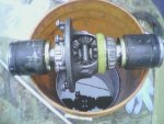
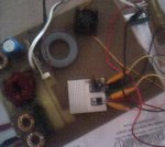
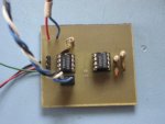
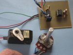
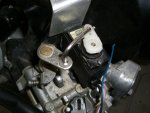
Well, I do believe I'm finally gonna start making my kart! I went to a local junk yard today with a friend to see what parts I could take out of a regular car that might be usable in a kart. I ended up taking the differential out of an older Nissan Sentra, which wasn't difficult to do as someone had already taken the engine and left the transmission just laying there. I'm hoping it's not too overkill for something like this, but I do want to use a diff and didn't really feel like spending $150 for one. For about $100 I ended up getting the diff, cv joints, a master cylinder, and a windshield washer fluid reservoir (to replace the broken one in my gf's car). I will take some pics of what I'm planning on using as soon as I can find the battery charger for the digital camera... figures, it's not available when I need it.
 

kibble

I banned myself
Messages
2,766
Reaction score
15
I had to resort to using my phone to take pics of my stuff. There's a pic of the engine I plan on using and there's a pic of the diff with the cv joints. I plan on modifying the cv joints somehow though.
 

Attachments

  • pic0019.jpg
    pic0019.jpg
    68.4 KB · Views: 197
  • pic0018.jpg
    pic0018.jpg
    66.8 KB · Views: 184

RobertD

Administrator
Staff member
Messages
3,018
Reaction score
74
Location
Texas
sounds good. Looks like a honda, or honda knockoff engine. I use one of those that's a 6.5, great engine.
 

kibble

I banned myself
Messages
2,766
Reaction score
15
It's actually a Subaru Robin engine, I didn't show the back where the recoil is but, it's supposed to be a 9hp engine. I ran it today for the first time since I got it and it sounds really clean. It idles really nice too, so nice that it hardly sounds like it's running. I was actually waiting for it to stall but it didn't. It was either this engine or the 11hp. The 11 is really noisy though.
 

kibble

I banned myself
Messages
2,766
Reaction score
15
So I was thinking of how to operate the throttle on the engine and I decided I don't really want to use a wire. What I will try to do instead is operate the throttle with an R/C servo. I would have to make some sort of mount for it but that shouldn't be too big of a problem. I will make a circuit board that has a potentiometer on it that attaches to the gas pedal. I was looking online yesterday for a schematic that would control a servo and I found one that looks simple and decent, I just have to build it now. Will post pics and maybe a video if it works like I want it to.
 

RobertD

Administrator
Staff member
Messages
3,018
Reaction score
74
Location
Texas
hmm. Just make sure the "default" position is off. I'd hate to see your RC crap out and you drive off a cliff.
 

kibble

I banned myself
Messages
2,766
Reaction score
15
Well the system for it is not going to be radio controlled, the servo is the type that's used in an R/C system but it's going to be controlled through some small wires. I was actually planning on also setting up a device that would detect if the servo stops responding to the input and would automatically shut off the engine. Yes, it's more complicated than just using a single wire to control the throttle but hey, that's what I do. I believe that if it works, fix it! You gotta be creative after all. I went and bought some of the chips I will need for the circuit board today. I will probably start making the board later tonight. Of course I'm gonna put the system through some thorough testing before I put it in use to make sure everything works as planned, safety is #1. I want to be able to enjoy what I made instead of riding once and ending up in the hospital! LOL :D
 

mikeandike

New member
Messages
232
Reaction score
3
can you send me the schematic for that? I'd like to take a look at it. For your circuit boards wut method do you use?
 

ryf

New member
Messages
309
Reaction score
2
I think this is an awesome idea.... my only thought would be to test it for a long time on stands (tires off ground) and make sure there isn't a problem that isn't instantly obvious. when you get electronics, things don't always do what you expect. so be careful and let us know what happens.
 

kibble

I banned myself
Messages
2,766
Reaction score
15
Oh yeah, I know. I've had things go "POP" many times and even catch on fire! If you look at the included pic, you can see an aluminum heatsink in the middle with a really dark spot on the top, right hand side. I was building a power supply and that was a MOSFET that couldn't take the stress I was putting it through and it literally caught on fire. Too bad I didn't have the camera when it was actually burning cause it was pretty cool! :p
 

Attachments

  • burnt.JPG
    burnt.JPG
    36.1 KB · Views: 80

mikeandike

New member
Messages
232
Reaction score
3
LOL. I was making a voltage regulator (really simple no mosfets or coils, 1 chip) and i had a big capacitor on it 4700uF 50v. It wouldnt decharge so i put it on a piece of metal and there was a big spark and it made a small dent in the plate. I also reversed the polarity on an op amp and it started smoking.

Anayways, I used to etch boards with sharpie marker but i wanted to try something new so i got all the stuff for a photo resist method (transparency film (you can get it @ an office place cheaper), florescent light (already had one) , a piece of glass (from a picture frame) and some developper (electronics store). All you do is draw something up on the computer (free cad things that suck) and print it. I believe it works better with a laser printer but my inkjet has a transparency film setting that works ok and you can reuse the paper again :p
 

kibble

I banned myself
Messages
2,766
Reaction score
15
Ah yes, making sparks with caps is always fun. I bought two 100V, 14,000mfd caps on ebay. Charged and touched to metal makes nice loud pops.

I have a laser printer that I could use to make the transparencies but I don't have the transparencies themselves. I remember I tried regular transparencies not made for laser printers once... that was fun, trying to get it out of the printer that is. I'll get to making photo boards eventually, in the mean time I use some etch resist dry transfers that I bought at radioshack to make all the pads for the components and then I draw in the traces with different thickness sharpies. I didn't get to work on my servo controller board yesterday but I did draw up the traces on a piece of paper so that I know how it's gonna be wired.
 

kibble

I banned myself
Messages
2,766
Reaction score
15
Finally got around to finishing up the servo controller board. It works great! Now all I have to do is find a way to attach it to the engine and test that out.
 

Attachments

  • IMG_0694.jpg
    IMG_0694.jpg
    45.8 KB · Views: 52
  • IMG_0695.jpg
    IMG_0695.jpg
    54.9 KB · Views: 56

ed1380

Banned
Messages
1,182
Reaction score
1
Location
ATL, GA
I'm pretty much uber stupid in electronics. is there anyway you can get a botom shot of the pcb?

I found this. can the jumper in the top left and bottom right be removed and just closed? what are they for anyway?
 

kibble

I banned myself
Messages
2,766
Reaction score
15
Here you go.

On that schematic, it appears that the two jumpers you're talking about are just test points so that you can test out the board with an oscilloscope. They aren't necessary and don't do anything other than that. If you were to build that board you can just ignore them as if they weren't there but you wouldn't want to jump the two points.

I made a mount for the servo to attach to the engine and I'll take pics of it once I've mounted it on the engine.
 

Attachments

  • servo-board.jpg
    servo-board.jpg
    50.7 KB · Views: 38

kibble

I banned myself
Messages
2,766
Reaction score
15
This is what the servo looks like attached to the mount and what the whole thing looks like assembled. The wire attaching the servo to the throttle is not the one that's gonna be used. It's only there for representation of how the two are gonna be attached together.
 

Attachments

  • CIMG2290.jpg
    CIMG2290.jpg
    39.6 KB · Views: 29
  • CIMG2289.jpg
    CIMG2289.jpg
    46.5 KB · Views: 25
  • CIMG2293.jpg
    CIMG2293.jpg
    51.4 KB · Views: 25
  • CIMG2292.jpg
    CIMG2292.jpg
    57.3 KB · Views: 46

kibble

I banned myself
Messages
2,766
Reaction score
15
I finished the servo-throttle linkage today and tried it out. It works!

Here's a small video of it in wmv format.
 

Attachments

  • CIMG2307.jpg
    CIMG2307.jpg
    54.9 KB · Views: 59
  • CIMG2306.jpg
    CIMG2306.jpg
    55.7 KB · Views: 53
Status
Not open for further replies.
Top