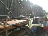
Electron Cross-kart

Functional Artist

Well-known member
Messages
4,411
Reaction score
1,694
Location
Toledo, Ohio
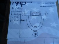
OK so, a 2-link set-up would cause the wheel to "tilt" during suspension travel
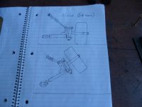
SAM_5094.JPG
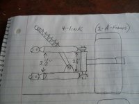
Whereas a 4-link set-up, would help keep the wheel more even with the road
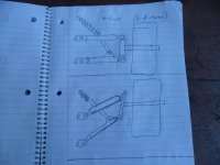
SAM_5095.JPG
...but, that's a lot of (kinda expensive) parts :eek:
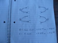
SAM_5096.JPG
Re-calculating
...re-calculating :popcorn:

It looks like Ima gonna, have ta make more A-frames :surrender:
...but, maybe re-designed ta be a bit more cost-effective
...maybe using DIY bushings ;)
SAM_5097.JPG
 

Functional Artist

Well-known member
Messages
4,411
Reaction score
1,694
Location
Toledo, Ohio
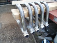
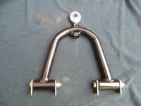
Been makin' some "new" A-frames

* I made (5) of em'
...just in case I :censored: (1) up
or
If all goes well
...I'll have a spare :2guns:
SAM_5114.JPG
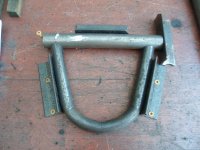
I set up a welding "jig"
...so, they all got welded up, the same
SAM_5105.JPG
* I welded the (2) "bushing holders" on as (1) long piece
...to ensure "near perfect" alignment

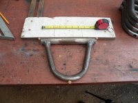
Then, set up a cuttin' "jig"
...to cut them "off", all the same :thumbsup:
SAM_5115.JPG
** I could have left the "bushing holders" as just (1) full length (8 1/2") piece
...but, then the A-frames would only be attached, to the frame, with (2) tabs
...(1) on the front side of the A-frame & (1) in the rear

But, by using (2) separate (2") bushing holders (on each A-frame)
...they are then, connected by (4) tabs, "doubling up" the attachment points (& strength) ;)
 

Functional Artist

Well-known member
Messages
4,411
Reaction score
1,694
Location
Toledo, Ohio
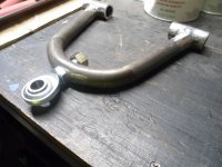
Next, I installed the "ball joints"
SAM_5126.JPG...then, welded the "nuts" on good
SAM_5151.JPG
They should be "good-n-strong"
...adjustable
...& changeable ;)
 

Functional Artist

Well-known member
Messages
4,411
Reaction score
1,694
Location
Toledo, Ohio
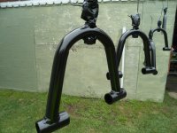
Cleaned the A-frames up & painted 'em (Satin Black)
...they should be about done so, I figured I'd seal 'em up :thumbsup:


SAM_5170 (1).JPG

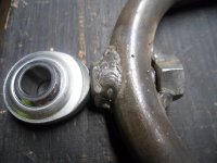
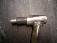
To make the "bushings", I cut (8) 2 1/8" long pieces of 1/2" ID rubber fuel line
...& (8) 2 1/8" long pieces of 3/8 ID steel tube (painted Satin Black along with the A-frames)

* The bushing holders are ~2"
...so, by making the bushings ~2 1/8" long, it should give us a little bit of clearance ;)

After the paint was dry, I just "slid" 'em together
SAM_5131.JPG
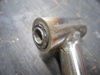
...assembled (notice the ~1/6" of the bushing protruding?) :cheers2:
SAM_5132.JPG
...& the complete unit (with tabs) ready for mounting :sifone:
SAM_5174 (1).JPG
 

Functional Artist

Well-known member
Messages
4,411
Reaction score
1,694
Location
Toledo, Ohio
Hey you'all how far apart should the A-frames be positioned?
...about the same, width or distance, as the spindle?
SAM_5180 (1).JPG

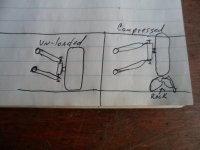
Also, should they be "in-line" with the frame? (when un-loaded)

It seems like I would get the most suspension "travel" if (when un-loaded) the A-frames were angled downward a bit?
...then, when the driver is in it, they would be closer to "level" (like in the upper pic)
...with ~1/2 of the "travel" range still available

SAM_5181 (1).JPG
Also, here is a video of progress so far :2guns:
 

WillMatrix

Member
Messages
251
Reaction score
22
Hey you'all how far apart should the A-frames be positioned?
...about the same, width or distance, as the spindle?
View attachment 133984

Also, should they be "in-line" with the frame? (when un-loaded)

It seems like I would get the most suspension "travel" if (when un-loaded) the A-frames were angled downward a bit?
...then, when the driver is in it, they would be closer to "level" (like in the upper pic)
...with ~1/2 of the "travel" range still available

View attachment 133985
Also, here is a video of progress so far :2guns:
You are always pushing the envelope!!! Great job.
 

Pinhead

Member
Messages
33
Reaction score
8
Location
Kansas
That type of suspension you are using is vulnerable to large levels of bump steer under rough conditions.

Maybe/kinda/sorta.

If the inboard pivot point of the tie-rod is on the same plane and in-line with the pivot point of the A-arm, you won't have any bump-steer.
 

Functional Artist

Well-known member
Messages
4,411
Reaction score
1,694
Location
Toledo, Ohio
I've been on a battery adventure (learnin' stuff) ;)

But, I've made a little progress on the Electron kart though :thumbsup:

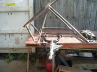
So, before installing the A-frame mounting "tabs" I did some "triangulating" of the frame (triangles make 'er "tougher") :2guns:
...& added a bar, for attaching the upper A-frame to
SAM_5494.JPG
Another angle
SAM_5496.JPG
Seems like it's only gonna have ~2" of "travel" :unsure:

Q: Is this about normal for a set up like this?
 
Top