Electrical ! OMG!

Status
Not open for further replies.

Larry D

New member
Messages
9
Reaction score
0
Location
Paradise, Ca
Hello all,

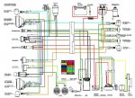
Newbie here. I am trying to get spark to my friends 2012 Kandi fs 150 ! WTH ever happened to color coding the wires! So far he has told me they replaced the ignition switch, cdi, coil and stator. What I need Is a diagram I can actually read ! I want to start with the ignition switch to make sure it is correctly wired. Does anyone have the actual diagram showing the wire colors and where they go ? LOL.
 

itsid

Moderator
Staff member
Messages
11,563
Reaction score
251
Location
Ruhrpott [Germany]
All diagrams I've seen so far have been color coded (letterwise since they're all B/W images!)

Show us what you got, and we see what we can do ;)

Also, those chinese gy6 buggies have like 12 different wires...
it's not too hard to trace a wire in the diagram to a known point and just write down it's color for future reference, is it?

THREAD MOVED!

'sid

PS if you'd not picked the wrong Forum and a more descriptive Subject, I'd be more willing to search for a diagram, you put no effort in your question, so I'm hesitant to spend another minute in doing the googling for you ;)
 

Larry D

New member
Messages
9
Reaction score
0
Location
Paradise, Ca
Hello and thank you for the reply ! I have two questions for you. The black and red wire coming from the stator, on the diagram it shows it going to the cdi. On the harness there is no where to put it. Can I upload some pics here to show you?

---------- Post added at 09:57 AM ---------- Previous post was at 09:55 AM ----------

Sorry, Where should I put the thread ? :oops:
 

gman3850

Member
Messages
405
Reaction score
4
Location
gilbert az
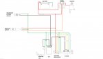
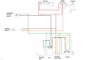
if u want to build your own harness here is a bare bones wiring setup
 

Attachments

  • Hammerhead.jpg
    Hammerhead.jpg
    107.4 KB · Views: 40

Larry D

New member
Messages
9
Reaction score
0
Location
Paradise, Ca
Hello again and sorry for the screw up!

I have one important question that I think will solve my problem. The black/red wire on the stator is not hooked in to anything. There is a red/white wire in the number six position on the the cdi box. All the diagrams I have seen show black/red going to power the cdi at pin six. So does the black/red wire coming from the stator need to be hooked up to pin six to power the cdi or is the wiring different for the 2012 Kendi 150 fs. Thank you gents for any answer.

---------- Post added at 01:11 PM ---------- Previous post was at 01:07 PM ----------

if u want to build your own harness here is a bare bones wiring setup

I think maybe at this point that would be the way to go!

---------- Post added at 01:18 PM ---------- Previous post was at 01:11 PM ----------

As you can tell I suck at wiring ! But I have to say the China wiring leaves nothing to be desired ! Three and four extra feet of wire just for the two front turn signals ! It is a accident waiting to happen, Then add in two and three people before me moving crap around turns it into a mess !
 

gman3850

Member
Messages
405
Reaction score
4
Location
gilbert az
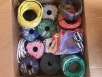
Hence why I took the time to take a completed wiring diagram and make it bare bones and my box of wiring
 

Attachments

  • IMG_3085.jpg
    IMG_3085.jpg
    371 KB · Views: 5

Larry D

New member
Messages
9
Reaction score
0
Location
Paradise, Ca
Let me ask the question this way. Have any one of you seen a cdi box power up without the black/red wire from the stator not connected ? And is it possible it does not need it because of the way it is wired?
 

Larry D

New member
Messages
9
Reaction score
0
Location
Paradise, Ca
Well with no reply's it looks like I am on my own. I still have not found a corresponding diagram for the 2012 Kandi fs 150. I thought for sure some one would have had the original. Until I can find it I am dead in the water. I will continue to search. my only other option is to make my own , but the owner does not want to pay for the labor. To many hands on this wiring. Pin #6 stands out with the red/white connected to it leaving the red/black from the stator in limbo. If anyone one by chance runs across the correct diagram it would be very grateful. ----:huh:
 

gman3850

Member
Messages
405
Reaction score
4
Location
gilbert az
every unit did theirs different, kandis, hammerhead, roketa, yerfdog, dazon, tao, sunl. So when seeking a diagram best place to look is that manufactures website, if non is given most likely they dont have a standardized set and were put together using off the self parts from other places.

Black with red if im not mistaken is the accessories wire, which doesnt always have to be wired from the stater based on the polarity. Dc i believe is a non connected system where ac is what my wiring harness is based off
 

Attachments

  • Hammerhead.jpg
    Hammerhead.jpg
    107.4 KB · Views: 10
  • twister wire.jpg
    twister wire.jpg
    97.7 KB · Views: 14

Rail rider

Inmate # 3192016
Messages
792
Reaction score
6
Location
Planet earth ( the flat one)
every unit did theirs different, kandis, hammerhead, roketa, yerfdog, dazon, tao, sunl. So when seeking a diagram best place to look is that manufactures website, if non is given most likely they dont have a standardized set and were put together using off the self parts from other places.

Black with red if im not mistaken is the accessories wire, which doesnt always have to be wired from the stater based on the polarity. Dc i believe is a non connected system where ac is what my wiring harness is based off

Dang mang, now you are just showing off with your grafix skills ...:roflol: :cheers2: :stir: :popcorn:
 

Larry D

New member
Messages
9
Reaction score
0
Location
Paradise, Ca
Still trying to get spark, one more question.

The three wires coming from the ignition. In all the diagrams I have come across it shows one of the the wires going to ground. The three wires in question are (red/yellow for starter) (red/white) and (solid red.) Can someone tell me if one of these go to ground ? What am I missing here ? Thanks for any help !!!
 

Larry D

New member
Messages
9
Reaction score
0
Location
Paradise, Ca
Hello Gman,

The ignition switch was missing due to a lost key. Someone used a toggle switch and a momentary button to make it run. Without the switch, I can't tell you if it was a two or three wire switch. To make matters worse the toggle and momentary were removed and sitting on the seat The owner states that it ran before he replaced the ignition switch from an automotive store. If that was the case then I do not understand why he had someone replace the cdi/coil/ stator. It is a cluster you know what! If I could only find a diagram with the color coded the wires I feel I could wire it correctly. The cutout pin was removed from the CDI as well. When I connect the red and the red/white wires together I see power going to the CDI box and the coil. So many hands on this thing are not making it easy being I suck at electrical. I can build engines, degree cams, port two strokes, tune and time. But electrical gets me every time.! LOL! Anything you can offer would be deeply appreciated. Thanks Gman---
 
Status
Not open for further replies.
Top