Electric Gokart for thesis

Status
Not open for further replies.

Flurky123

New member
Messages
34
Reaction score
0
Location
Belgium
Hello everyone,

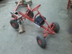
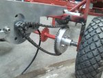
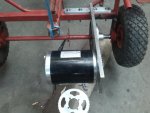
Today I worked a lot on my electric gokart. There are 2 problems: - There is a bolt in the way of the chain. I'm basically going to turn the furthest point of the motor up. This will lift the chain so the bolt is in the middle of the chain.

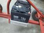
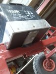
- My collegue made the motor holder out of 10mm aluminium. I don't think it'll be strong enough. Any opinions? A way to make it stronger? I thought about simply welding a plate to the other side of the motor and put in a bolt.


See pictures for details.

Greetings
Flurky123
 

Attachments

  • IMG_20140607_204704.jpg
    IMG_20140607_204704.jpg
    76.7 KB · Views: 9
  • IMG_20140607_204714.jpg
    IMG_20140607_204714.jpg
    75.3 KB · Views: 7
  • IMG_20140607_204725.jpg
    IMG_20140607_204725.jpg
    85.6 KB · Views: 8
  • IMG_20140607_204752.jpg
    IMG_20140607_204752.jpg
    83.1 KB · Views: 8
  • IMG_20140607_204804.jpg
    IMG_20140607_204804.jpg
    75 KB · Views: 8

OzFab

Well-known member
Messages
15,615
Reaction score
70
Location
Warwick Qld, Australia
Ideally, the best way to solve the problem is to remake the bracket so the mounting holes run in a straight line from the centre of the axle. A simpler fix is to mill out half the depth of the channel so the head of the bolt fits inside, thus, reducing its height...

Questions: Why is the motor mounted so far back? Who decided that was the best position to mount the motor?
 

Flurky123

New member
Messages
34
Reaction score
0
Location
Belgium
Ideally, the best way to solve the problem is to remake the bracket so the mounting holes run in a straight line from the centre of the axle. A simpler fix is to mill out half the depth of the channel so the head of the bolt fits inside, thus, reducing its height...

Questions: Why is the motor mounted so far back? Who decided that was the best position to mount the motor?

Well: we have to get this finished by the 20th of June. Yes I know we're late.

And to your question: we are working on this with 2 persons and the other one made the motor bracket. I know, it's not the best position.

But do you think i'll be strong enough? The motor give a lot of torque (3.2Nm). The 10mm thick aluminium doesn't seem to be so strong.

Thanks
Flurky123
 

itsid

Moderator
Staff member
Messages
11,563
Reaction score
247
Location
Ruhrpott [Germany]
the bracket will be okay...
3.2 Nm is not much over the length of the holder the weight of the motor is affecting it more than it's torque.
but to free the chain, you should shorten it as much as possible (it's one cut plus another weld.. no big deal ;)

The only other option I can think of at the moment is, a hard rubber roller (with a bearing insert) directly mounted onto the bolt (well longer bolt...you know) that forces the chain down the bearing then will reduce the stress a bit;
although that's the passive side it's still not ideal but it should work.

'sid
 

Flurky123

New member
Messages
34
Reaction score
0
Location
Belgium
Hello everyone,

I'm almost done, today I did my first run. After fixing a lot of bad contacts and even creating a short circuit (not paying attention) I finally managed to make it drive.

NOTE: There's no brake and I still have the throttle in my hands. I have to mount this once.

I really want to thank you all. It was a pleasure to meet you guys. I will still put some video's on here of the final product.

And Itsid: The 10mm aluminium isn't strong enough. I can see the bracket pulling down when accelerating. The chain isn't as thight as it was in the beginnen as well, yes because of the stretch, but it's the bracket as well. Well find something to fix this, I've already got a plan.

Greetings
Flurky123


https://www.youtube.com/watch?v=KtT-cHqDcik
 

Flurky123

New member
Messages
34
Reaction score
0
Location
Belgium
Hello everyone.

Today I mounted all the things together. Gave throttle a place, got some support for my feet, etc.

Now a problem occured. I don't seem to know what it is. It has something to do with the trottle. I connected red to red, black to black and green to green. Nothing happens when I push the throttle. I do have 4.6V between red and black. As soon as I disconnect black or green, the motor goes full throtlle. Anyone knows what happens here?


Greetings
Flurky123
 

itsid

Moderator
Staff member
Messages
11,563
Reaction score
247
Location
Ruhrpott [Germany]
you swapped signal and voltage on the throttle.

check the labels and/or manuals for what color code is used.
chances are your signal line is red *shrugs*

if you don't find labels and don't have a manual, test the amatures...
disconnect the throttle to do so;

first the controller:
get a multimeter between red and black should be 5V (not 4.6 .. 5!)
now test between red and green for resistance should be above 2kOhms.

So you now know the controller is wired to common standards (black -5, red +5, green(or blue) signal)

now the throttle:
get the mutlimeter (resistance mode) between red an black;
should be below 20Ohms, croscheck all three wires against each other.
One should be high resistive against the others.
that's the signal line.
the other ones should be obvious (either it's balck for negative or red for positive.. maybe both)
if it's indeed just as you already connected it, the throttle may be faulty.
(unlikely.. but still possible)

Now, connect just the voltage wires to the controller, leave the signal line unconnected.

power up your kart and measure the voltage of your signal line (throttle side) against ground (most likely black)
should be zero!
push the throttle down and it should raise to about 5V (4.6 is common here)

'sid
 

Flurky123

New member
Messages
34
Reaction score
0
Location
Belgium
Hello,

I don't think I made wrong connections. Everything worked already with these connections. It's pretty straight forward: red to red, black to black, green to green. Between red and black I've got 4.6V, I measured it. Resistance between red and green is very high (Mohms) and between red and black it's around 1 Kohm. Whatever I do, I do not get any signal on the green wire.

A few people already had a look at it and more and more it seems to be the throttle that is broken. Nothing actually happened to the throttle, no wire got interrupted, we've opened it and there is no more than 2 magnets, a spring and a sensor with the 3 wires. We don't see why or how it became broken.

The strange thing is that it already worked. By evening after some welding it just doesn't work, and everything was disconnected while welding.

Maybe I have to find a new sensor? Although this will be hard to replace internally.

Greetings
Flurky123
 

itsid

Moderator
Staff member
Messages
11,563
Reaction score
247
Location
Ruhrpott [Germany]
welding?

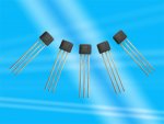
Hmm.. you may have fried the chip (that's the actual hall sensor)
Maybe an arc jumped maybe it was fired due to heat .. but it's toast I'm afraid :(

you can either buy just the sensor (farnell, digikey, conrad electronics etc) if you can read the make and model, or you buy a new throttle.

'sid
 

Flurky123

New member
Messages
34
Reaction score
0
Location
Belgium
Well, we're affraid the sensor has given life. But I still can't seen how it has been roasted. I mean, when welding, it was at a relatively safe distance and everything around is seems to be from plastic.

But yes, you're never sure.

My brother is looking for a replacement sensor, I'm in the exams now :(

I hope it's easy to put together, because of the little space and little lenght of cable inside the pedal.

Greetings
Flurky123
 

itsid

Moderator
Staff member
Messages
11,563
Reaction score
247
Location
Ruhrpott [Germany]
well, find the exact same sensor, solder new wires to it and it will fit.

Again, might be something that seems unrelated
(a jumping arc desn't need to hit the sensor, it's enough if it found it's way to one of the wires)

A hall effect sensor can die at temperatures above 60°C, the plastic around it will not melt with temperatures twice as big.

*shrugs*

Oh next time: use a connector, no flying wires! That's always bad and will cause troubles at one point.

'sid
 

OzFab

Well-known member
Messages
15,615
Reaction score
70
Location
Warwick Qld, Australia
This happens all the time in the auto industry; some goose will do some welding on a car without disconnecting the battery &, because the whole electrical system is grounded on the body of the car, ZAP goes the electrical system...

That's probable what happened; the motor is mounted to a metal bracket which connects to the metal frame... see where I'm going?
 

Flurky123

New member
Messages
34
Reaction score
0
Location
Belgium
In the end I think you guys are right. It's completely unexpected. The only way of getting to the sensor was via the motor or a flying arc.

Thank you guys, I'll try to find a new sensor and solder it to eachother.

Itsid: I know what you mean by the flying wires. Actually it's a temporalily option. I ordered a 3-pin connector from tnc as well, but I need 2 :( I think I'll connect them with a kind of connector (in dutch 'suikertje' means 'sugar') :p

Thanks a lot
Flurky123
 

Flurky123

New member
Messages
34
Reaction score
0
Location
Belgium
Hello,

I can't seem to find the exact same sensor. I know the part number, but I don't know anything about the make of the sensor.

I did some research however and I find a lot of Honeywell products. If the sensor has the same specifications, it should work? Right?

The other option would be to contact tncscooters and ask if they know where I can find the exact same sensor. It's probably some Chinese make

Greetings
Flurky123
 

itsid

Moderator
Staff member
Messages
11,563
Reaction score
247
Location
Ruhrpott [Germany]
So it's either a nana electronics sensor (chip discontinued in 2010)
or a Jinhua Super-Chip Microelectronics sensor (View attachment 20120829164707231.pdf)
both are not available in any electronics shop I can think of.

Sorry.

if it's the Jinhua
20100927144448858.jpg

you can refer to the pdf linked above to find a matching replacement,
it's a chinese pdf.. so that'll cause some troubles;
but an electronics guy can still detect the necessary informations and compare them ;)

'sid
 

Flurky123

New member
Messages
34
Reaction score
0
Location
Belgium
Hello,

My brothers friend could take care of a hall sensor. We looked just at the input/output voltage to be 3.6-6V. When I came home from exams my brother already soldered the new sensor to the wires. And it works again, I'm so happy :p

Tomorrow i'll have to defend everything I did to a jury. They'll give me points on my explanation and work. I'll upload a video over the course of the week.


Thank you all very much, without you I couldn't have done this. And I learned a **** of a lot in this project. Most importantly: always double check + and -, in a hurry I changed + and - (because both wires were blue ... ) and I created a short with a flame of around 15cm :p . That's one thing not to forget.


Greetings
Flurky123
 
Status
Not open for further replies.
Top