Driven pulley keeps pinching belt…

710E

New member
Messages
11
Reaction score
13
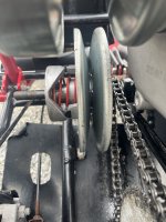
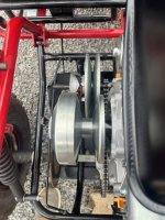
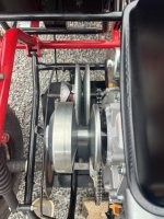
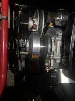
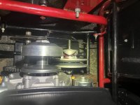
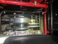
I’m very new to the go kart world but quickly learning more than I thought that I ever would. With that said Im having a real struggle with what appears to be a comet 40 series torque converter in a Manco 710. I had the go kart lifted off of the ground and the torque converter seemed to work nicely. However when I sat down to ride it would only go 2 feet before the belt jammed in the driven pulley. Both pulleys have been taken apart and cleaned. The driver looked almost brand new so it was lubed with dry lube and reassembled. The driven pulley seems to look ok all be it I’m not entirely sure what Im looking for. The base of the pulleys were lined up perfectly which caused the alignment of the belt to be off so I opted to keep the belt centered in the pulleys as opposed to the base of the pulleys being perfectly in line with each other. My questions are…. Do I have the driven pulley on backwards because Ive head some yes and no’s on how its installed. Second is the drive belt on the 40 series tapered on both sides? Any help would be appreciated because there is a wealth of knowledge on here. The pictures are from the rear and top looking down respectively.
 

Attachments

  • IMG_1043.jpeg
    IMG_1043.jpeg
    1.3 MB · Views: 13
  • IMG_1045.jpeg
    IMG_1045.jpeg
    1.6 MB · Views: 13
  • IMG_1046.jpeg
    IMG_1046.jpeg
    1.6 MB · Views: 13

Sparkwizard

Well-known member
Messages
525
Reaction score
621
Location
Richlands ,NC USA
Since neither your driver or driven has a "flat" side, they are both angled, so it should have a belt tapered on both sides.
Can you get a good picture of the driven assembly? I'll make a guess, but the real experts will need a semi close-up to help you figure it out.
 

710E

New member
Messages
11
Reaction score
13
Absolutely! I included a couple of pictures to show what the pulleys would look like aligned with the backing plate vs what they would look like aligned with the grooves.
 

Attachments

  • IMG_1048.jpeg
    IMG_1048.jpeg
    1.6 MB · Views: 13
  • IMG_1049.jpeg
    IMG_1049.jpeg
    1.7 MB · Views: 8
  • IMG_1050.jpeg
    IMG_1050.jpeg
    1.5 MB · Views: 9
  • IMG_1051.jpeg
    IMG_1051.jpeg
    1.7 MB · Views: 9
  • IMG_1052.jpeg
    IMG_1052.jpeg
    1.7 MB · Views: 10

JimD

Well-known member
Messages
324
Reaction score
697
Location
Naperville, IL
Ramp is on the wrong side for an outboard mount. Wrong spring or flip it around 180 degrees so the ramps are next to the engine. In your picture I consider that an outboard mount but based on the way the ramps move you would have to reverse that unit to have it work correctly.
 

710E

New member
Messages
11
Reaction score
13
Thank you Jim. Excuse my ignorance but Im a little confused on what the ramp is? If its referring to the tapered part of the pulleys they are both tapered so I might need a more elementary explanation of what you meant.
 

Sparkwizard

Well-known member
Messages
525
Reaction score
621
Location
Richlands ,NC USA
The three little black nylon things on the hub of your driven ride on the ramps. Belt pulling on the pulley should force the nylon bumpers against the ramps, not away from them. The way they are set up would cause the pulley to open too fast.
 

710E

New member
Messages
11
Reaction score
13
Wonderful thank you for the picture excome and the simplified explanation spark. I had marked what side of the ramp it was before I disassembled it so maybe it was wrong from the get go! I will try switching them around and go from there. As for the alignment of the pulleys Im assuming its more critical for the belt to be in alignment than the pulleys themselves?
 

710E

New member
Messages
11
Reaction score
13
Ill give it a shot tomorrow and see if that is the solution! I will also try that for the alignment.
 

panchothedog

Well-known member
Messages
2,792
Reaction score
3,748
Instead of flipping it around ( sometimes that leads to all kinds of clearance and alignment problems ) install a reverse wound spring. That will put the ramps
( I call them the points of the cam ) but you know what I mean, on the other side of the plastic stops. It's about 15 bucks. OMB Warehouse sells them. As set up right now, your driven clutch ( the one we're talking about ) was going into high gear range as soon as you touched the throttle.
 

710E

New member
Messages
11
Reaction score
13
That makes perfect sense Pancho. So I took the driven pulley off when I got it, marked it, put it back and now found out it is backwards. My question is why would it all of a sudden be backwards? I replaced a subaru/ robin for a predator. Im assuming they both spin CCW as viewed from the shaft? Im also assuming that would make a difference if they turned different directions?
 

Hellion

Moderator
Messages
8,640
Reaction score
3,715
My question is why would it all of a sudden be backwards?

It looks like that is an easy thing to do; taking off the driven assembly makes the parts loose and out of relation to each other (they lose their proper index if you're not careful?)? I am not certain about this, being a novice on the topic.
 

Sparkwizard

Well-known member
Messages
525
Reaction score
621
Location
Richlands ,NC USA
It looks like that is an easy thing to do; taking off the driven assembly makes the parts loose and out of relation to each other (they lose their proper index if you're not careful?)? I am not certain about this, being a novice on the topic.
There is a big snap ring that holds the assembly together when you take it off of the jack shaft. If that snap ring is removed, you have a small puzzle of parts.
 

panchothedog

Well-known member
Messages
2,792
Reaction score
3,748
The direction that the spring is wound has everything to do with how it locks into the clutch base, and on which side of the plastic stops the cam points end up. If you are pulling them ( the cam points) into the plastic stops, the clutch will open up immediately and instantly be in high gear range. If you are pulling them away from the stops, then the clutch will work as intended. Gradually opening up as speed increases. I don't know why they are not manufactured with the reverse wound spring. This delama catches MANY 40 series customers off guard. Causes a lot of frustration, as it is a natural tendency to mount the clutch with the spring packet ( snout ) outward. And it will not function in this orientation. A little shout out for OMB Warehouse. When you buy the 40 series converter from them,
( like I did ) they include the reverse wound spring in the kit. Still, I feel strongly that the manufacturers should build them differently. Put it so it works for the
90% of users, and if some want to install it with the snout inward, let THEM change the spring.
 

panchothedog

Well-known member
Messages
2,792
Reaction score
3,748
There is a big snap ring that holds the assembly together when you take it off of the jack shaft. If that snap ring is removed, you have a small puzzle of parts.

Changing the spring is really not very difficult. Not that many parts inside. If you even pay half attention to what you are doing, you'll be fine. Hardest part is the snap ring. A cheapy set of snap ring pliers ( the kind with the changeable ends) won't be robust enough. A medium duty fixed set, and presto! Off it comes.
 

710E

New member
Messages
11
Reaction score
13
So if I put the snount inboards towards the motor it will function as intended? (I already ordered a reverse wound spring from OMB) This would just be a temporary fix until the spring gets here.
 
Top