Double A-Arms with u joints?

Status
Not open for further replies.

The_Machine

New member
Messages
136
Reaction score
0
Location
GA/AL
LOL blaz, we are going in a circle again. that picture is single a arm of my first buggy project, hence why I said "for example" when referring to single A arms. :)

That buggy was more of a high strength utilitarian deal. Now it's on to beautifully engineered parts and perfection. When you ride something around for so long you just can't wait to work with patience and create something new, beautiful, and precise.

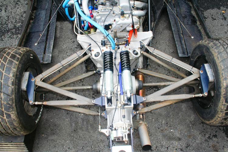
Formula Student is much like Formula SAE, except european. I did a lot of my research on their documents and by asking questions in their forums and have already designed the front end. It's a complete mindfxck without seeing the arms in motion. Without Inventor I would have surely spent more time unbolting and redesigning arms throughout the process.

The only thing I am so unsure of is the effect of roll center without actually knowing the exact roll rate of the kart and spring rate. Probably something I will ignore for now and try to keep the center of gravity as low as possible, then learn about through actually driving it. It will probably be stiff enough to ignore, though.

Right now parts are coming in and I will begin this week. Built a welding table and improv shop in the basement where it is nice and cold all summer long, but it probably wont take me but 2 months or less to complete. I will start a build thread this week.
 

The_Machine

New member
Messages
136
Reaction score
0
Location
GA/AL
Just looking at stuff like this, doesn't it just give you an instant boner and your brain ticking?


Because I am cheap I will probably be saving some cash on components such as the rims and tires. maybe some 20 inch ribbed el cheapos. 20 heim joints and threaded weld bungs are expensive! And for now, no all around disc, just rear.
 

Blazkowiez

Kart Aficionado
Messages
2,538
Reaction score
47
Location
Houston, Texas
Yeah dude, I understand we're being counterproductive (or at the least I am). That picture is anything but a go-kart and looks somehow expensive... What is really funny is I'm almost hoping the back end of that beast looks somewhat similar.
 

The_Machine

New member
Messages
136
Reaction score
0
Location
GA/AL
Oh heck no. very expensive. for instance, streamlined tubing is 3 or 4 x more expensive than chrome moly. The back end will be the same as far as suspension goes. Spring placement might be different, most likely vertical.

Because of the light weight I will be putting a honda rebel twin cylinder 250 in it to start. When I get tired of the power it'll get a bigger engine and an upgraded driveline, if it needs it.
 

sideways

Unfinished projects king.
Messages
1,501
Reaction score
2
Location
Perth, Western Australia
Use the uni joint/driveshaft as the top A arm, many vehicles have and it is usually quite effective.

In all seriousness, if you going to have a vehicle with 4" of ground clearance then your only going to have inch or two of suspension travel, the camber change on wide based single A arms is going to be negligible. To make dual A arms more effective than wide based single A arms you would have to have unparallel, unequal length dual A arms for which complicated formulae is need to figure out proper dimensions that will work the best.

You could use macpherson struts, less camber change than single A arms but much more complicated to produce.

And another thing, don't skimp on tires, good tires will do more for you handling than clever suspension ever will...

The_Machine said:
Just looking at stuff like this, doesn't it just give you an instant boner and your brain ticking?

Oh hell yes!

Thanks

Hayden
 

theo

New member
Messages
872
Reaction score
1
For 2 or 3" of travel you can get away with equal a arms and by using rod ends on the a arms, you will be able to adjust toe and camber. The hardest and costly part with dual a arms is building the outer bearing housing, this needs machining. Also the a arms will have to be design to eliminate axle plunge.

I would go along with sideways, for 2 or 3" of travel go with single a arms. With them you will have a deg. or so of negative camber at your full compression which would be great in cornering. And use rod ends at the inboard mount this will allow you to adjust toe. Much cheaper to build, google formula V for pics. and ideas.
:thumbsup:
 

The_Machine

New member
Messages
136
Reaction score
0
Location
GA/AL
I am using rod ends at every pivot. 3/8 on the inners, 1/2 on the outers.

Theo, you said the outer bearing housing for the rear needs to be machined, but I think I may take 2 flange bearings and bolt them back to back on either side of the plate. flangettes require 2 plates and complicate the design. Other than those 2 options I don't know of a bolt on or weldable bearing product that takes up little space and can hold a short length of axle 90 degrees perpendicular to the kart. Do you?

Streamlined tubing?

Just out of interest, why pushrods?

Not using streamlined tubing, that's just how expensive they are.

Pushrods require another element of design and put the center of gravity lower. Also, I can potentially add anti-roll very easily if needed. I think the weight of the cranks and the pushrod will cancel out the center of gravity deal, but it's just something I want to do.

Unequal unparalleled arms are already in the design. Wish I could show you but inventor will not open for me anymore.

Don't feel like modeling and measuring out everything on the computer as there are always suprises when dealing with feet clearance and comfort so I will build the base of the frame and situate things on it, then redesign the arms for a wider track if the original wheelbase changes.
 

theo

New member
Messages
872
Reaction score
1
You could use something like a AZUSA bearing hanger and bolt a flanget bearing and brackets to it one front and one back with say 1/2" spacers. This would give you around 2 1/2 to 3" of area for the stub shaft. All you have to do then is to think of something to weld on the top and bottom of the hanger for the a arms to attach.
 

The_Machine

New member
Messages
136
Reaction score
0
Location
GA/AL
1/4" plate sandwiched between 2x 2bolt 1" shaft flange bearings is 3.05 inches. stronger, cheaper, easier to adapt, but only slightly heavier.


Are you suggesting putting 2 azusa bearings between 2 flangette clamps?
 

theo

New member
Messages
872
Reaction score
1
Are you suggesting putting 2 azusa bearings between 2 flangette clamps?[/QUOTE]

nope.
 

theo

New member
Messages
872
Reaction score
1
A bearing with the flangets, spacer, the bearing hanger, a spacer then another bearing and flanget. Three hole not 2 hole flangets.
 

The_Machine

New member
Messages
136
Reaction score
0
Location
GA/AL
OK. I get what you're saying.

Quick rough model of the 2 bolt flange idea without a mount point for the toe adjustment bar.


theo

New member
Messages
872
Reaction score
1
That will most likely work, but you need 2 mounting points on the bottom at least. Nothing to stop that housing from pivoting.
 

theo

New member
Messages
872
Reaction score
1
So are you making a 3 link setup? Can you show a drawing of the complete suspension assm.
 

modelengineer

Lord of the noise
Messages
1,609
Reaction score
2
Location
Sydney, Australia
(Forgive me if you know all this, it's hard to tell over the internet)
To evaluate a double wishbone suspension design you need to work out the following:

KPI
Castor
Static camber
Camber gain in bump and roll
Scrub radius
Roll centre height
Roll centre movement with respect to chassis, vertical & lateral, in bump and roll
Location of the instant centre
Ackerman %
Virtual swingarm length

You can do this using inventor, a free DOS program called WISHBONE.EXE if you can find it, or a string computer, as described by Staniforth in his book "Competition Car Suspension"

Google will be your friend in finding out any of these terms if you don't know them. I've just gone through this whole process while designing the front suspension for my next project, which is a road registered race car with a 2.5L Subaru engine.

*EDIT* found the link for WISHBONE.EXE
http://www.locostusa.com/yahoo/Wishbone_setup.exe
You will need to run it in a DOS emulator, I use DOSBox and it works well. Some instructions on how to use the program can be found here:
http://locostusa.com/forums/viewtopic.php?f=5&t=1438
 

The_Machine

New member
Messages
136
Reaction score
0
Location
GA/AL
I've spent several weeks studying suspension geometry and visualizing it in Inventor and have a formula sae student to answer any questions I have. It's a black art, that's for sure.

Just found this. Very useful for visualization.

http://www.racingaspirations.com/?p=286

As of now, though, I need to start on the build and define the wheelbase before I can begin on the front suspension.
 
Status
Not open for further replies.
Top