Custom front spindles

Status
Not open for further replies.

5814SpeedCo

Member
Messages
150
Reaction score
2
Location
Fort Worth, TX
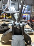
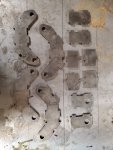
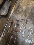
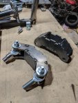
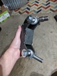
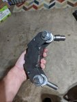
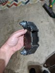
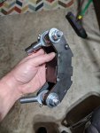
Got my custom built spindle parts in the mail yesterday for my daughter's off road kart build. All made from 1/4" steel. They will be beefy and be able to take a beating!! Can't wait to get them welded up! After that I will make the new a-arms for it.

These are designed to use heim joints along with high-misalingment spacers for max turning angle. Got a few other goodies cut out and in the mail yesterday to help adapt ATV wheels to it.
 

Attachments

  • Resized_Resized_20200122_180635.jpeg
    Resized_Resized_20200122_180635.jpeg
    811.8 KB · Views: 16
  • Resized_Resized_20200121_191219.jpeg
    Resized_Resized_20200121_191219.jpeg
    878.3 KB · Views: 15

5814SpeedCo

Member
Messages
150
Reaction score
2
Location
Fort Worth, TX
Center hole distance is 6" and just over 3" wide. The steering mount will be figured out after these are welded up and put on the kart. I have a rack and pinion steering I will be using as well that is 11" wide. Should be a good handling kart when it's done!

The front wheel hub plates are made for trx400 front wheels and got a hub bearing tube from BMI karts that will be welded to them. Also will be welding in the bolts to the hub plates.
 

5814SpeedCo

Member
Messages
150
Reaction score
2
Location
Fort Worth, TX
These things are going to be beefy!!! I need to get the axle bolts for them before I can tack on the front plate. May also looking into getting another batch laser cut for a better fitment without having to grind on them due to some slight beveling while being plasma cut. But for now they are going together really good and I'll get the steering portion once they are on the kart.
 

Attachments

  • IMG_20200215_193825.jpg
    IMG_20200215_193825.jpg
    381.7 KB · Views: 5
  • IMG_20200215_193941.jpg
    IMG_20200215_193941.jpg
    264.8 KB · Views: 6
  • IMG_20200215_193948.jpg
    IMG_20200215_193948.jpg
    247 KB · Views: 6
  • IMG_20200215_193955.jpg
    IMG_20200215_193955.jpg
    253.3 KB · Views: 6
  • IMG_20200215_194001.jpg
    IMG_20200215_194001.jpg
    274.7 KB · Views: 3

5814SpeedCo

Member
Messages
150
Reaction score
2
Location
Fort Worth, TX
the fourth pic looks almost like a brembo brake caliper ;)

'sid

Can't say that I've seen a Brembo caliper look like that. Either way I should have theses finished up by next weekend. Still have to make the a-arms for them and get a few more heim joints and threaded inserts.
 

anickode

Active member
Messages
2,296
Reaction score
15
Location
S.E. Michigan
It's a nice simple design for sure. Any concerns about the steering angle being too limited by the range of motion of the heim joints? Most have about a 15-20° effective range of angular motion which isn't much for steering. Typically you'd see them set up with radial motion for the steering axis.
 

Bansil

Painter of gnomes....
Messages
1,360
Reaction score
914
Location
Mnts of the farthest NE TN you can go
Not knocking you, but why does everyone make the assembly notches when the fitment is so bad with plasma? I see a lot of it on plasma sites. Most of the parts wouldn't be any harder to mockup with clamps and 123 blocks?

Oh....I am curious because I am waiting on my plasma table to ship and have a bunch of parts I plan to cut out like you would with conventional cnc mill, I come from cnc mill, lathe and edm world (day job and tired of cut off wheels and grinders at home) :popcorn:
 

5814SpeedCo

Member
Messages
150
Reaction score
2
Location
Fort Worth, TX
It's a nice simple design for sure. Any concerns about the steering angle being too limited by the range of motion of the heim joints? Most have about a 15-20° effective range of angular motion which isn't much for steering. Typically you'd see them set up with radial motion for the steering axis.

I have high-misalingment spacers added in, I have 56 degrees total range of motion, it's the same range of motion that Protodie uses on their front spindles. I did a lot of research and design simulation before making the final decision.

---------- Post added at 05:58 PM ---------- Previous post was at 05:51 PM ----------

Not knocking you, but why does everyone make the assembly notches when the fitment is so bad with plasma? I see a lot of it on plasma sites. Most of the parts wouldn't be any harder to mockup with clamps and 123 blocks?

Oh....I am curious because I am waiting on my plasma table to ship and have a bunch of parts I plan to cut out like you would with conventional cnc mill, I come from cnc mill, lathe and edm world (day job and tired of cut off wheels and grinders at home) :popcorn:

I work at a place that does CNC plasma and Oxy-FUEL cutting. These were cut by a friend up north on a small at home plasma table. Needed them rushed as we are backlogged at work right now. We have a hi-def 5-axis plasma table that would out a better edge on the parts. If I do another batch I will do it at work.

The notches were just to see if it would do good or not. It does help but yes there was some grinding involved.
 

anickode

Active member
Messages
2,296
Reaction score
15
Location
S.E. Michigan
Not knocking you, but why does everyone make the assembly notches when the fitment is so bad with plasma? I see a lot of it on plasma sites. Most of the parts wouldn't be any harder to mockup with clamps and 123 blocks?

Oh....I am curious because I am waiting on my plasma table to ship and have a bunch of parts I plan to cut out like you would with conventional cnc mill, I come from cnc mill, lathe and edm world (day job and tired of cut off wheels and grinders at home) :popcorn:

You should see high resolution plasma cutting. Narrower kerf, nearly perfect square edge profile, and much faster and cheaper to run than laser.

Even standard plasma cutting can be incredibly precise when done on a good table with the right consumable setup and proper programming.

---------- Post added at 08:58 PM ---------- Previous post was at 08:54 PM ----------

Here you can see the spacers and range of motion

Not too bad I guess I'm partial to a little tighter turn radius myself, but to each their own. :cheers2:
 

5814SpeedCo

Member
Messages
150
Reaction score
2
Location
Fort Worth, TX
It will be trial and error but I think with adding some negative camber to it, it should steer pretty good. At least that will be easy to adjust. If it proves not to steer that great then a quick redesign, make the parts at work for dirt cheap...if not free!

We cut some 3/16" steel today on our high-def 5-axis plasma cutter and the edges came out super clean and were some pretty intricate parts.
 

Bansil

Painter of gnomes....
Messages
1,360
Reaction score
914
Location
Mnts of the farthest NE TN you can go
Amazing machines, i have a customer/vendor...lol...that does 5 axis laser work on class 8 truck fender liners and such, wow...technology has gone cray,cray. **** their waterjet table can fit a full size truck or 2!
 

5814SpeedCo

Member
Messages
150
Reaction score
2
Location
Fort Worth, TX
Here is a 3D simulation I did in Solidworks for the design of the spindle. I've added about 7-9 degrees of negative camber to it, that's what you side the inside face of the spindle when it turns. If not then you wouldn't see any at all, we'll see how this translates into actual function once everything is up and running.

https://www.youtube.com/watch?v=uH_BIaqori0
 
Status
Not open for further replies.
Top