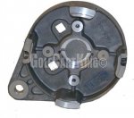
Curtis 1204M-4201 Controller Assembly

Status
Not open for further replies.

sean miller

New member
Messages
21
Reaction score
0
Hi

I recently purchased this assembly. http://www.nocoev.com/product/1204M-4201_assemblage.htm

I also picked up an Advanced DC Motor which is serially wound.

The light current circuit diagram is pretty straight forward.

The heavy current however is not straight forward and I am confused and do not want to proceed until I get some direction.

A1, A2, S1, S2 on motor. Positive and negative on battery pack and B+, B-, A2, M- on the controller all need to be connected and I would imagine the order of connection might be a factor too.

Can anyone help me with this one, please.

Thank you for reading.
 

itsid

Moderator
Staff member
Messages
11,563
Reaction score
247
Location
Ruhrpott [Germany]
Well, "A" stands for Armature (the rotor basically) and "S" is the stator coils.

you can bridge A2 and S1 and you have a simple two poled DC motor
with plus and minus just like in your old toys.
connecting plus to A1 make it turn one, connecting it to S2 the other way around;
that easy.

The controller takes the direction switching for you, and that's why it looks confusing ;)

B+ and minus should be obvious, they take the battery connection.

A2 (Armature) connects to A2 on the motor (oh loose the bridge I was talking about)

A1 on the motor is also connected to B+ on the controller (or the battery.. but I suggest a controller connection for simplicity)

So half way there ;)

Now the hard part, the M- connection on the controller.

That connects to the direction switch whichever it is you'll use.
basically it goes like this:

M- is connected to a toggle switch connecting either M- to S1 or S2
while at the same time bridging A1 of the motor to the other stator terminal S2 or S1


If you do not want/need reverse, just ignore that.
connect M- to S1 and bridge S2 to A1.
if the motor turns the wrong way around
M- to S2 and S1 to A1.

and you're done!


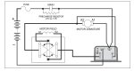
PS here's a simple setup with a simple forward/reverse switch..
to get a better idea.
mechanical-reverse.jpg

'sid
 

sean miller

New member
Messages
21
Reaction score
0
Thank you Sid

I have the instructions from the maker of the assembly and I am including them here for you and anyone who might buy this assembly in future.

Installation Instruction CURTIS DC Series Motor Controller Assemblage
1. Checking the controller assemblage, battery system and motor:
a) The whole assemblage status
b) Installation kit & mating connectors
c) Battery charging status
d) Motor status (turning manually 2-3 rounds)
e) The cables’ length and insulation conditions
2. Preparing the mating connectors (please identify the wire number corresponding to the connectors on assemblage and throttle, as shown in the diagram found at http://www.nocoev.com/product/1204M-4201_assemblage.htm

a) Throttle connector:
i. If there is a throttle switch before the key switch, link the No. 3 wire to the throttle
switch output; If not, link the No.3 wire to the key switch output
ii. Link the No.4 wire marked as “B+” or
iii. Link the No.1 wire
iv. Link the No.2 wire
b) Assemblage connector:
i. Link the No.1 wire
ii. Link the No.2 wire
iii. Link the No.3 wire
iv. Link the No.4 wire
v. Link the No.5 wire
vi. Link the No.6 wire
to the Forward / Reverse switch “power in” terminal (possibly “Input”, please verify your F / R switch codification)
to the assemblage mating connector No.6 wire
to the assemblage mating connector No.2 wire
to key switch input terminal
to the throttle mating connector No.2 wire to the key switch output terminal
to F / R switch Forward output terminal
to the key switch output terminal
to the No.1 wire of throttle mating connector
NOCO
Website: http://www.nocoev.com - Email: noco@live.cn

vii. Link the No.7 wire to F / R switch Reversing output terminal
viii. The No.8 wire could be linked to “0V” (B-), or be spared
c) Try to connect and disconnect the connectors, making sure the all terminals are well
contacted.
3. Mounting the assemblage and throttle on board. If there is an earth line, connect it to the
assemblage aluminum plate.
4. Connecting all cables of battery and motor to the assemblage.
a) Do not supply power to assemblage till confirming there is no “B+” and “B-” connection reversed. The reversed power poles’ connection could cause an immediate system damage.
b) Keep the F / R switch at neutral position, and the throttle at low end without output. Keep the vehicle braked.
c) There are labels on the assemblage, indicating the connecting position, “B+”, “B-”, “D1”, “D2”, “A1” and “A2”.
i. We use “D1” and “D2” for motor field studs, while some DC series motor
manufacturer use the symbols “S1” and “S2”.
ii. “B+” and “B-” for battery positive and negative poles.
iii. “A1” and “A2” for motor armatures.
5. Deliver power to the assemblage. Normally there should be a “click” sound of main contactor at the moment of power arriving.
6. Turn on the key switch, and keep the throttle at low end without output. Moving the F / R switch handle (or pushing the Forward / Switch buttons), check if the F / R contactor works by hearing the “click” sounds.
7. Release the vehicle brakes, put the F / R switch at “forward” position, step down a little the foot pedal (throttle) to start the motor. If the motor works, stop the motor, and try the same to reverse the motor.
8. Increasing slowly the motor speed till its max limit, run the vehicle for 5 minutes. Stop the vehicle, turn off the power, check the motor situation (if there is any overheating) and the assemblage (overheating or over-current).
9. By identifying there is no abnormal noise or smell, the system is installed correctly.
 

sean miller

New member
Messages
21
Reaction score
0
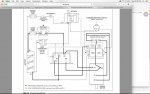
I found a connection diagram in an older curtis manual.

My question is as follows: If someone stuck to the light current connections from NOCO but ignored the heavy duty wiring diagram and connected it in the following manner:

1. S1 to A2 on Motor to A2 on controller
2. S2 to Controller M-
3. A1 to controller B+ to Battery B+
4. Controller B- to Battery B-

What would likely be the cause for the FWD and reverse solenoids clicking but the motor not engaging?
 

Attachments

  • curtis_1204.jpg
    curtis_1204.jpg
    70.4 KB · Views: 4

itsid

Moderator
Staff member
Messages
11,563
Reaction score
247
Location
Ruhrpott [Germany]
hm.. if it's not a faulty motor contactor or battery ..

chances are you flipped the S-terminals...

so check again if S1 and S2 are connected correctly.

'sid
 

sean miller

New member
Messages
21
Reaction score
0
I hope I did not fry the controller. I was in a hurry and I should not have proceeded to connect based on incomplete instructions... My bad. I did not smell any burning but did notice an electrical clap when I connected the negative terminal on the battery in that configuration.

I swapped S1 and S2 where they attach to the F/R CHANGEOVER CONTACTOR with no joy.

I bridged S1 and A2 and attached A1 to negative battery and S2 to positive 12V only and the motor turns. That rules out battery or motor.

What else can I check to isolate the problem Sid?
 

itsid

Moderator
Staff member
Messages
11,563
Reaction score
247
Location
Ruhrpott [Germany]
Uhm, for testing.. that's okay, but you are aware that the controller expects the armature to be the PLUS side of the battery, correct?

actually, for most (if not all) motors that shouldn't make much of a difference, but sticking with the manual is always a good idea when you want to rule out as many errors as possible ;)

Now the contactor 'fires' as soon as the throttle is detected (i.e. not 0 volts for a pwm throttle)
BUT that doesn't mean it's actually moving... (I think the threshold should be around .5-.7Volts)
without a throttle the contactor shouldn't click (or you have a short), but of course the motor will still not turn :D

So next thing.. detach then redo your throttle connections,
be precise (are you using a potbox or a pwm throttle?)

when in doubt post pics or at least color codes and model of the throttle.

'sid
 

itsid

Moderator
Staff member
Messages
11,563
Reaction score
247
Location
Ruhrpott [Germany]
Ah.. sorry...
yes, you said so in your first post..

Well, so the question is, did you follow their instructions?

i.e.
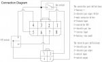
Throttle (4Pin); Controller (8Pin)
Throttle-1 to Controller-6,
Throttle-2 to Controller-2,
Throttle-3 to Controller-3 and Controller-5 (and the key switch),
Throttle-4 to F/R switch-in (F/R switch-outs to Controller-4 and Controller-7)
like that:
NOCO-ASSEMBLY-CONNECTION_s.jpg

'sid
 

sean miller

New member
Messages
21
Reaction score
0
Sid - I got it running. It turned out to be a loose connection!

Now the motor, which I have on its end with shaft facing up, is sparking when it turns. It seems to be rubbing stator to rotor.
 

itsid

Moderator
Staff member
Messages
11,563
Reaction score
247
Location
Ruhrpott [Germany]
Uhm yeah.. very few 'big' electric motors actually like running with a vertical shaft.
brushed motors tend to spark since the brushes are not perfectly aligned with the commutator then.

post a pic of the motor, if it comes with a front cap, lay it down to test it.
(most golf cart motors do not have a front cap.. they MUST be attached to a gearbox or equipped with a cap to run safely; that end of the shaft needs a bearing to!)
if not, don't test while it's not enclosed.

If it sparks laying on it's side, give it a minute to align the coils, it should center the shaft between the coils and the sparking should vanish...
If not, it can be anything from humidity to dirt.

If you happen to have a compressor sitting in your shop, then you might be able to get rid of that.

'sid
 

itsid

Moderator
Staff member
Messages
11,563
Reaction score
247
Location
Ruhrpott [Germany]
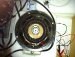
uncapped golf cart motor..

please DO NOT test that motor too often or too intensively (high speeds)
the slightest imbalance can and will go haywire.
if the armature crashes into the stator coils at speed, it'll not only rip the coils,
it might rip your face (tiny shrapnels of metal flying right out!)

Motors like that MUST BE run with either the cap, or the gearbox attached.

That shaft you see needs a bearing at that end to prevent wobbling.

really... do not test that motor again without!
You've been lucky that nothing happened yet.. don't court disaster :eek:

'sid
 

sean miller

New member
Messages
21
Reaction score
0
Sid - thanks for the warning. I do not want to have an accident.

Any idea where I can purchased the end cap for this motor?
 

itsid

Moderator
Staff member
Messages
11,563
Reaction score
247
Location
Ruhrpott [Germany]
Well, not knowing Make and Model.. nope.

But I'm afraid I have to warn you... for some such motors there is no cap.

Motorcompanies often sell the same motor in both configurations,
once for golf cart transaxle (gearbox) without a cap, and also capped for other applications.
If that's the case for your motor, then you can find the model number of the "regular" version, and get the end cap as a spare part.

Some companies though make nothing BUT golf cart motors like yours, they do not make end caps at all;
and although the diameter and bolts are more or less the same on most models,
it's not said that you can find a matching part on another maker's shelf :(
Also you'll need a shaft extension to have a shaft outside the then closed case...

Some DIYers made a cap from a matching but broken gearbox (cutting away all unneeded material)
and while that's almost always a viable route, it's sometimes not the cheapest way to do so.
Others simply have machined a face plate to fit a bearing and allow the armature to be fully supported.
That too is not cheap unfortunately if you don't have access to a machine shop.
(and it requires a lot of patience and precision)

So, maybe you should check if you can sell your motor to someone looking for a golf cart motor, and buy yourself a similar motor that's already completely encased *shrugs*
Might be the least of all evil.

But let's see.. what's the make and model we talk about, or at least specs
output Wattage and rpms.. as well as
diameter and length.

'sid
 

sean miller

New member
Messages
21
Reaction score
0
Its a Advanced DC Motor model 73445G01.

Thank you in advance for advising on different avenues open to me.
 

itsid

Moderator
Staff member
Messages
11,563
Reaction score
247
Location
Ruhrpott [Germany]
Sorry, I can't find the match..
but I'm sure there is one... (nearly 100% sure ;))

and the reason is simple, AMD (advanced motors and drives) makes Fork lift motors.. they are capped..
("drive end plate" is the technically correct term I think)
unfortunately, I don't find a website or verified phone number.. countless used car dealers with the same or similar name :(

Anyways.. AMD 140-07-4001 has a 'drive end plate' that I think would match your motor.
can't tell for sure *shrugs*

thinking about it.. I think you could even get a commutator end plate
7911-2T.jpg
(wrong motor, just as an example)

install a matching bearing and break through the center to get to the splined hub.. diameter will be identical, and the boltholes should be too *shrugs*

'sid
 
Status
Not open for further replies.
Top