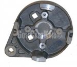
Thank you Sid
I have the instructions from the maker of the assembly and I am including them here for you and anyone who might buy this assembly in future.
Installation Instruction CURTIS DC Series Motor Controller Assemblage
1. Checking the controller assemblage, battery system and motor:
a) The whole assemblage status
b) Installation kit & mating connectors
c) Battery charging status
d) Motor status (turning manually 2-3 rounds)
e) The cables’ length and insulation conditions
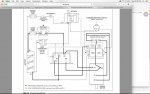
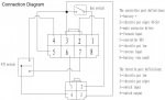
2. Preparing the mating connectors (please identify the wire number corresponding to the connectors on assemblage and throttle, as shown in the diagram found at
http://www.nocoev.com/product/1204M-4201_assemblage.htm
a) Throttle connector:
i. If there is a throttle switch before the key switch, link the No. 3 wire to the throttle
switch output; If not, link the No.3 wire to the key switch output
ii. Link the No.4 wire marked as “B+” or
iii. Link the No.1 wire
iv. Link the No.2 wire
b) Assemblage connector:
i. Link the No.1 wire
ii. Link the No.2 wire
iii. Link the No.3 wire
iv. Link the No.4 wire
v. Link the No.5 wire
vi. Link the No.6 wire
to the Forward / Reverse switch “power in” terminal (possibly “Input”, please verify your F / R switch codification)
to the assemblage mating connector No.6 wire
to the assemblage mating connector No.2 wire
to key switch input terminal
to the throttle mating connector No.2 wire to the key switch output terminal
to F / R switch Forward output terminal
to the key switch output terminal
to the No.1 wire of throttle mating connector
NOCO
Website:
http://www.nocoev.com - Email:
noco@live.cn

vii. Link the No.7 wire to F / R switch Reversing output terminal
viii. The No.8 wire could be linked to “0V” (B-), or be spared
c) Try to connect and disconnect the connectors, making sure the all terminals are well
contacted.
3. Mounting the assemblage and throttle on board. If there is an earth line, connect it to the
assemblage aluminum plate.
4. Connecting all cables of battery and motor to the assemblage.
a) Do not supply power to assemblage till confirming there is no “B+” and “B-” connection reversed. The reversed power poles’ connection could cause an immediate system damage.
b) Keep the F / R switch at neutral position, and the throttle at low end without output. Keep the vehicle braked.
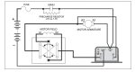
c) There are labels on the assemblage, indicating the connecting position, “B+”, “B-”, “D1”, “D2”, “A1” and “A2”.
i. We use “D1” and “D2” for motor field studs, while some DC series motor
manufacturer use the symbols “S1” and “S2”.
ii. “B+” and “B-” for battery positive and negative poles.
iii. “A1” and “A2” for motor armatures.
5. Deliver power to the assemblage. Normally there should be a “click” sound of main contactor at the moment of power arriving.
6. Turn on the key switch, and keep the throttle at low end without output. Moving the F / R switch handle (or pushing the Forward / Switch buttons), check if the F / R contactor works by hearing the “click” sounds.
7. Release the vehicle brakes, put the F / R switch at “forward” position, step down a little the foot pedal (throttle) to start the motor. If the motor works, stop the motor, and try the same to reverse the motor.
8. Increasing slowly the motor speed till its max limit, run the vehicle for 5 minutes. Stop the vehicle, turn off the power, check the motor situation (if there is any overheating) and the assemblage (overheating or over-current).
9. By identifying there is no abnormal noise or smell, the system is installed correctly.