Controller Diagram

aerona87

New member
Messages
3
Reaction score
0
Good evening,
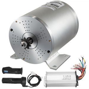
I had a question about a controller setup. I'm looking at buying a 2KW motor from Amazon that comes with a controller. Here is the diagram for the controller. I just had a couple questions to make sure I understand what goes where. I did see a post from May 2021 that was similar to this, and I did learn a few things from it.

Battery and Motor Phase- Self Explanatory
E-lock- essentially the on/off switch
Reverse- another 2 position switch

My main questions are:
1) Do I need a Hall sensor if I am using a foot pedal?
2) What is the 3 speed functionality? Does it limit max speed or does it act as a simple throttle?
3) What is the brake functionality? I planned on using a brake pedal that is attached to mechanical brakes.
4)Brake lights/indicator lights- does the controller automatically step down voltage? Or will they be the same voltage as my battery?

Here is the link to the motor and controller.
Snip20210822_2.png

Thank you!
 

Functional Artist

Well-known member
Messages
4,406
Reaction score
1,686
Location
Toledo, Ohio
Howdy :welcome2:
1. The Throttle (foot pedal) connects/plugs into the speed controller
...the Hall sensor connects/plugs into the motor
The (3) motor phase wires send the "power" to the motor
...& the Hall sends the rotor position "signal" back to the controller

2. The (3) speed switch/plug (electronically) limits the RPM's of the motor
...IIRC low is ~ 50% RPM's, med is ~75% RPM"s & high releases the motors full RPM capability :thumbsup:

3. The "brake' is usually connected to a switch (connected to the brake pedal)
...when the brakes (& switch) are activated, the speed controller "cuts" the power going to the motor
...& sends "power" to "turn on" the brake light (if equipped)

4. the power for most accessories is usually the full "pack voltage"
...most speed controllers do not have a "built in" voltage "step down" to operate 12V for lights

*Just wire (4) 12V lights "in series" for a 48V system ;)
 

aerona87

New member
Messages
3
Reaction score
0
Thank you for the info; this was perfect. My last question would be about the brakes. Are they assuming a front and rear brake system, hence the two connectors? For the brakes, I would use a band brake with a spring(switch) connected to one of the "brake" connectors on the controller (to cut motor power) and then connect lights directly to the "brake lights" connector which will get powered when the brake pedal is depressed and the spring/switch is shut. I think that is what you were referring to.

Thanks again!
 

Functional Artist

Well-known member
Messages
4,406
Reaction score
1,686
Location
Toledo, Ohio
Thank you for the info; this was perfect. My last question would be about the brakes. Are they assuming a front and rear brake system, hence the two connectors? For the brakes, I would use a band brake with a spring(switch) connected to one of the "brake" connectors on the controller (to cut motor power) and then connect lights directly to the "brake lights" connector which will get powered when the brake pedal is depressed and the spring/switch is shut. I think that is what you were referring to.

Thanks again!
Yup :cheers2:
...you got it :thumbsup:
 

benaj

New member
Messages
4
Reaction score
6
Location
Chicago, IL
I recently purchased a 2kw system from Vevor that essentially uses the same controller (motor controller model BY15WF-02-A but looks identical to yours posted above). I used a combination of 48v brushless controller diagrams found on internet, YouTube videos and my own multimeter testing to map everything out on mine when bench testing before installation.

The three way circuit appears to be (medium - high - low) when wired to a three way (on - off - on) switch. This I assume was to upgrade from the older controllers that would default to medium speed if no switch was attached to this connector. With my controller the default is high when no switch is attached. Depending on your goals, you may be able to just test this with jumping black with yellow and then black with blue to verify that no connection is the high top speed with your connector.

In regards to your question about why two brake connectors, I believe the logic is that many of these kits will be used on scooters and those have both right and left handbrake levers. You want squeezing of either of those brake levers to activate the braking motor-cut/brake light feature on the controller. I can confirm that both the indicator light and brake light connector output pack voltage, uncertain as to amperage lights they will support. My son really wants a full LED light bar in the front of his kart.... optimistic at best without the use of a relay circuit.

One last helpful hint, my kit's motor/controller combo ran the motor clockwise and like yours had no white wire "learn" connector (like many other controllers include to reverse the direction of the motor). If you are planning on running this kit on a go kart with the traditional chain left of motor, you will need to get the motor to run CCW in the forward direction. The reverse feature runs the motor slower than lowest forward speed and is not affected by the 3 speed selection. To get the motor to spin CCW in the forward direction you will need to find the proper combination of switching hall sensor wires and motor phase wires. With my kit the successful combo was switching the yellow and blue (fat) motor phase wires and then switching the yellow and green (thin) hall sensor wires.

Good luck. Let me know if you have any other questions.

Ben

BTW, if you haven't checked out some of the instructional videos from EV - Customs YouTube channel, go have a look. I found them very helpful early on, esp the ones from his BLDC Controller Learn Board series, part one here:
 
Top