carter bros. 2506-3016

Status
Not open for further replies.

emsman1

New member
Messages
18
Reaction score
0
Location
Rhode Island, USA
Just picked up my first father/son kart project from craigslist. Kart runs but does need some love and a tune-up.

Lights don't work and the remote kill switch doesn't work. I'm having trouble finding a wiring diagram for the kart and the engine (OHH60-71157D). Any help?
 

Attachments

  • 00c0c_22DImAz31sG_600x450.jpg
    00c0c_22DImAz31sG_600x450.jpg
    30.2 KB · Views: 46

emsman1

New member
Messages
18
Reaction score
0
Location
Rhode Island, USA
I understand there is not much wiring on these karts, but given its our first one and that it was neglected, I wanted to verify connections. I'm starting to understand the connections a little better after finding some "parts lists".

The lights don't work and I connected them to a battery to test. I want to replace them with something like this: Ebay LEDs or Harbor Freight Lightl. Thoughts? Spot or Flood?

Also, it looks like the brake rod is not routed correctly. I would assume it needs to be supported through the bracket in the picture?

Attached are the pictures of the wires off the motor and the brake area.
 

Attachments

  • 20150813_112035065_iOS.jpg
    20150813_112035065_iOS.jpg
    87.1 KB · Views: 24
  • 20150813_112125675_iOS.jpg
    20150813_112125675_iOS.jpg
    78.2 KB · Views: 15

afremont

New member
Messages
148
Reaction score
1
Location
houston
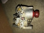
The kill switch is likely going to go to a wire that connects to the magneto coil. There will be a little tab sticking off the coil that a spade connector should plug onto. The kill feature operates by grounding this connection. That stops the spark from operating. I'm not sure how the light generator works exactly. You should be able to safely find the kill lead by experimentation. Assuming that the engine starts now, I would experimentally connect one lead at a time to engine ground, and then attempt to start the engine. When it doesn't start, that should be the kill wire. Alternatively, you could remove the pull start shroud and find the wire that leads to the little tab on the coil that I was describing. That would be the kill wire.

As for the light generator, I'm assuming that there is another coil that the permanent magnet flys by that generates a voltage. Unless there is a diode and/or some kind of regulator in it, it's just going to generate an alternating current on one of the leads with respect to ground, or possibly be an entirely isolated from ground circuit on 2 wires, I don't know. Here is some information that may help you figure it out:
http://www.smallenginesuppliers.com/html/engine-specs/briggs/briggswiringexplanation.pdf

Obviously, I'm assuming that you have a Briggs and Stratton engine. If not, then the pdf file isn't likely to be of much help. Removing the shroud should make it easier to figure out. The ignition coil is usually outside the flywheel, I have no personal experience with where the lighting coil is mounted. It could be outside or underneath I suppose. Unfortunately, I have no engines here at my home that have lighting capabilities.

EDIT: I want to add that I wouldn't try the trial-and-error grounding thing with the engine running as you could "possibly" cause damage to the lighting circuit by grounding it. I don't know that for a fact, somebody else probably does and hopefully they'll chime in, but if it were me, I would only try it the way I said since you're not likely to generate enough current to hurt anything just by pulling the rope. I would have the plug wire disconnected and use a tester to see if it is generating spark so that the engine doesn't actually start when pulling the rope. IMO, your best bet is to remove the shroud and trace the wire to the coil to find the kill wire.
 

emsman1

New member
Messages
18
Reaction score
0
Location
Rhode Island, USA
Thanks afremont. I will have to carefully experiment with the kill switch wiring.

I did find, via the parts list (Tecumseh OHH60-71157D ) that the engine does have an alternator coil (3 Amp DC - 5 Amp AC). Provided it's still working I assume I can hook up the LED lights to the 3 Amp DC wire (red). I will test tonight with a meter.

Need to determine brake rod routing. Tonight begins the power-washing and dissemble to refurbish.
 

afremont

New member
Messages
148
Reaction score
1
Location
houston
I'm sorry. I had made the incorrect presumption that it was a Briggs engine. That really shouldn't matter on how the kill wire works, but it certainly invalidates the pdf file that I linked to.

Since you say that it has a DC output, I now take it that your cart originally had a battery? If so, then the DC wire would have gone to charge the battery and the AC wire would likely be your lighting power.

EDIT: I didn't notice the model number in your original post. I looked it up and was checking it out on partstree.com. That's an interesting motor. It seems to have overhead valves. I'm not sure what the displacement is, but I'm guessing that it might be larger than 200cc. I would guess that the yellow lead coming from the stator is the lighting wire, since it is higher current but I don't know that for a fact. If there is a green wire in there, my guess would be that it is the engine kill wire.
 

emsman1

New member
Messages
18
Reaction score
0
Location
Rhode Island, USA
Okay, I think after disassembling the kart I figured out the brake rod does need to go through the bracket for support.

The current brake band does not fit in this configuration. Does anyone know what the measurement from eyelet to eyelet on a 5" band should be? I want to confirm the current band is wrong before I order a 5" one.
 

Poboy kartman

Senior Moments Member
Messages
12,461
Reaction score
69
Location
White Settlement Texas
Well, I was looking for side views of that side. I can't see from overhead as the rods function is to collapse the band...and we can't see how the rod is routed linearly to the mounting post and active side of the brake band.

(Or even see the brake bands relationship to the drum.....other than its lined up.)
 

emsman1

New member
Messages
18
Reaction score
0
Location
Rhode Island, USA
Okay, now that I have the tire off, I will take a picture tonight.

Any idea of brake band measurement?


Well, I was looking for side views of that side. I can't see from overhead as the rods function is to collapse the band...and we can't see how the rod is routed linearly to the mounting post and active side of the brake band.

(Or even see the brake bands relationship to the drum.....other than its lined up.)
 

emsman1

New member
Messages
18
Reaction score
0
Location
Rhode Island, USA
Here is a picture of the linkage routed through the bracket (this is the way I think makes sense). I need to order a 5" brake band as I believe what was on there before was too small.

No onto engine issues. I replaced the filters, oil, and plug and cleaned the carb. It ran okay before with wrong plug installed, black oil, and black clogged filters. Now with new everything, I can only get it to run if I hold open the throttle. It will not idle.

I think instead of rebuilding, I'm going to order a replacement from Amazon for $16 (aftermarket). It gets good reviews.

Only issue is my breather tube goes into a hole in the air filter bracket and the new carbs have breather tube inlets in them. My carb does not. I figure I can plug the hole in the mount.

Thoughts on the carb issue?

New carb: Amazon Link
 

Attachments

  • 20150820_030030927_iOS.jpg
    20150820_030030927_iOS.jpg
    90.1 KB · Views: 8
  • 20150820_033833144_iOS.jpg
    20150820_033833144_iOS.jpg
    72.9 KB · Views: 6

emsman1

New member
Messages
18
Reaction score
0
Location
Rhode Island, USA
The saga continues. Replaced the carb with the Amazon one and it runs/idles great.

Trying to take the 2 piece rims apart to paint/replace tubes has been the hardest thing yet. The tires have literally welded themselves to the rims with rust. I've tried pb blaster, boiling water, force, etc. and nothing can get them off. I've only had luck with 1 side of the back, but that's it. Anyone else have any ideas?
 

OzFab

Well-known member
Messages
15,615
Reaction score
69
Location
Warwick Qld, Australia
If the rims are rusted that much, I would suggest you replace them...

As for removing the tyres from the rims, large flat screwdrivers, chisels, anything you can get between the rim & tyre to lever the two apart; it may take time but, you'll get there eventually...
 
Status
Not open for further replies.
Top