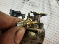
Carburetor thread... jets & stuff...

DavidBoren

Member
Messages
32
Reaction score
8
First off, I would kind of like to get an idea of which carbs everyone is using... the jets you have found that work best... and the displacement/rpms of the engine the carb(s) is being used for.

I believe it was Voltaire that said we must first define our terms, so I will lead with a simple format example we can use as a template going forward...

Displacement: 166cc
RPM: ~3100
Carb type: constant velocity [Keihin]
Carb size: 18mm
Jetting: 55/35
E-tube (if applicable):16166-Z8B-901
Clip position: non-adjustable
Fuel screw: non-adjustable
Air screw: not applicable

I think that covers most of the basic carb specs. Feel free to add more info, and obviously not everything needs filled out... it's not a test.

Secondly, I would like to know your guys' approach to tuning [your carbs]... play by ear? Read plugs? Data logging with sensors? Do you follow any particular tuning theory like Rich of Peak vs Lean of Peak?

And last, but not least, perhaps discuss what changes you have made that required tuning the carburetor to compensate... new air filters or intakes or exhausts... compression or timing or ignition changes... anything that required a change to be made to the carb. What was the modification that prompted tuning the carb, and what was the tuning solution done to the carb (jetting changes, etc)?
 

DavidBoren

Member
Messages
32
Reaction score
8
I just came across an online article talking about carb theory... particularly the Webers found on old Porsche 911's... a few things I found interesting is that Weber refers to their emulsion tubes as "brakes". Apparently, as rpms increase, the faster flowing air creates quite the draw on the main circuit... and fuel needs time to mix, emulsify, and vaporize.

So, the emulsion tube draws air down towards the main jet in order to start that mixing process with the fuel before it enters the venturi. Another thing I found interesting in that article I read; it stated that the air exiting the ports in the emulsion tube into the fuel can reach supersonic velocities, to give you an idea of what forces are at play here... and why "brakes" might be required within this circuit. Otherwise, the mixture would get progressively richer as rpms increase.

Fuel flow is physically slowed by the restriction the emulsion tube, itself, provides within the bore the fuel flows through after leaving the main jet. Fuel flow is also virtually slowed by the addition of air, which leans the fuel that is flowing. The outside diameter of the emulsion tube can be changed to provide more or less restriction at different points vertically along its length, and the size/location of the ports can also be altered to affect specific points in the rpm range.

There is a point where the draw is so great, that there is no time for fuel to accumulate between the outside of the emulsion tube and inside of the bore the emulsion tube resides in... at this point you are completely at the mercy of the main jet's flow capacity... and the emulsion tube is simply adding air into the fuel from all its ports as the fuel rushes by.

The article also talked using air jets to affect timing... a lot of us with less sophisticated carburetors do not have air jets that can be changed... but I thought it was cool how you can affect the timing of the vacuum signal that draws fuel through the circuits. Larger air jets shorten the duration and lean the mixture, with the reverse being true of smaller air jets.

Despite the random punctuation mistakes, I enjoyed the article and found it quite informative, overall. Here's the article, for anyone that may be interested...
http://www.performanceoriented.com/performance-tuning-2
 

pearl111

Well-known member
Messages
1,103
Reaction score
391
Location
Baltimore, Maryland
I just came across an online article talking about carb theory... particularly the Webers found on old Porsche 911's... a few things I found interesting is that Weber refers to their emulsion tubes as "brakes". Apparently, as rpms increase, the faster flowing air creates quite the draw on the main circuit... and fuel needs time to mix, emulsify, and vaporize.

So, the emulsion tube draws air down towards the main jet in order to start that mixing process with the fuel before it enters the venturi. Another thing I found interesting in that article I read; it stated that the air exiting the ports in the emulsion tube into the fuel can reach supersonic velocities, to give you an idea of what forces are at play here... and why "brakes" might be required within this circuit. Otherwise, the mixture would get progressively richer as rpms increase.

Fuel flow is physically slowed by the restriction the emulsion tube, itself, provides within the bore the fuel flows through after leaving the main jet. Fuel flow is also virtually slowed by the addition of air, which leans the fuel that is flowing. The outside diameter of the emulsion tube can be changed to provide more or less restriction at different points vertically along its length, and the size/location of the ports can also be altered to affect specific points in the rpm range.

There is a point where the draw is so great, that there is no time for fuel to accumulate between the outside of the emulsion tube and inside of the bore the emulsion tube resides in... at this point you are completely at the mercy of the main jet's flow capacity... and the emulsion tube is simply adding air into the fuel from all its ports as the fuel rushes by.

The article also talked using air jets to affect timing... a lot of us with less sophisticated carburetors do not have air jets that can be changed... but I thought it was cool how you can affect the timing of the vacuum signal that draws fuel through the circuits. Larger air jets shorten the duration and lean the mixture, with the reverse being true of smaller air jets.

Despite the random punctuation mistakes, I enjoyed the article and found it quite informative, overall. Here's the article, for anyone that may be interested...
http://www.performanceoriented.com/performance-tuning-2
If this is article is true for my stock pred. 212 carb. and other clones, then it gives me a better
understanding of the emulsion tubs and how they work.
Also helps when upgrading the carburetor and components.
 

karl

Well-known member
Messages
2,363
Reaction score
548
Location
North east Ohio
I usually tune by plug reading and throttle response. I try to go slighty rich
for some safety margin as I run 10 to 1 + compression ratio mostly.

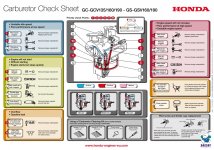
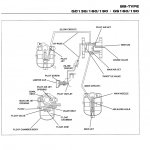
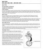
I don't have a whole lot to add, but Ill leave these here incase it is of any help.
 

Attachments

  • bawls.jpg
    bawls.jpg
    358.7 KB · Views: 19
  • bawls2.jpg
    bawls2.jpg
    122.2 KB · Views: 18
  • bawls3.jpg
    bawls3.jpg
    264.1 KB · Views: 19

DavidBoren

Member
Messages
32
Reaction score
8
I especially liked that article explained how the location of the ports vertically along the emulsion tube in relation to the level of the fuel in the bowl affects the timing that you switch circuits being used. Understanding that, and even better yet, being able to somewhat control when that switch occurs is just awesome. The article even encourages experimenting with it on your own by soldering existing holes closed, and drilling new ones. It is just a hollow brass tube, after all... it's not rocket surgery. Lol.

That article also reiterated that ports affect rpms opposite of their position vertically along the emulsion tube... ports high on the tube affect low rpms, and ports low on the tube affect high rpms. This is important to understand before one starts drilling holes all willy-nilly.
 

DavidBoren

Member
Messages
32
Reaction score
8
@karl, thank you for those pictures... I already had the color-coded Carburetor Check Sheet, but not the other two documents. I am still very new to tuning carburetors, and so every little bit helps.
 

DavidBoren

Member
Messages
32
Reaction score
8
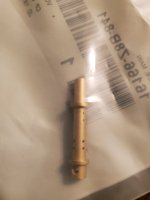
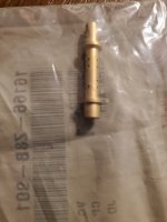
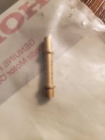
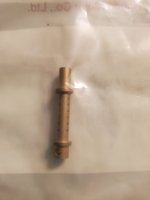
I have found four different emulsion tubes available for my carburetor. They all appear to have identical external dimensions, just different porting arrangements. Each one has four vertical rows of holes located between an upper and lower shoulder. The rows are spaced 90* apart around the emulsion tube, and alternate in order any time the rows contain different numbers of ports. Opposing rows always have the same number of ports, assuming they drill straight through the emulsion tube to create two rows of holes with one drill operation.

Of the emulsion tubes I have found in the 16166-Z8B family:

The 841 has two rows of four holes, and two rows of two holes.

The 901 has two rows of four holes, and two rows of three holes.

The 911 has four rows of five holes.

The WA1 has four rows of six holes.

The 841 and WA1 have two ports at the bottom, below the lower shoulder that I believe would supply more fuel to the pilot circuit.

The 901 and 911 do not have the extra ports below the lower shoulder.

I will try get some decent pictures posted later.
 

DavidBoren

Member
Messages
32
Reaction score
8
One of these days... I am going to change my main jet from the 055 to an 065, and probably swap my 901 emulsion tube for the WA1. I have not taken my carb apart, yet, so I actually am just going off parts diagrams for the 055 main jet and 901 emulsion tube said to be present in my carburetor. We will see...

I like the WA1 emulsion tube quite a bit. The extra ports below the lower shoulder supplying fuel to the pilot circuit seems like a good idea, and I like that the WA1 has ports at the same level as the fuel in the bowl. Those ports at the same level as fuel in the bowl should make for the quickest possible switch from the pilot circuit to the main circuit.

As of right meow, I have not yet bought a larger pilot jet... nor have I found an adjustable fuel screw for my particular carb. She starts fine, and that's literally all that circuit is used for. The engine spends no real time at idle, so abandoning the pilot circuit as soon as possible seems like the best course of action.

Well, the best course of action would be to pick up a larger pilot jet and an adjustable fuel screw... and I am not really pressed for time. I would like to have an assortment of different main jets and pilot jets, on top of my collection of emulsion tubes. And I do very much want to find an adjustable fuel screw that fits my carburetor [preferrably before I start messing with my carburetor, at all].

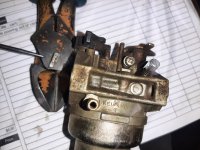
Anyone know which adjustable fuel screw fits the Keihin 18mm carburetor Honda uses om their relatively recent small engines? Mine, of course, is capped with a stopper, and is designed to snap its head off before readily adjusting in or out.
 

karl

Well-known member
Messages
2,363
Reaction score
548
Location
North east Ohio
Anyone know which adjustable fuel screw fits the Keihin 18mm carburetor Honda uses om their relatively recent small engines? Mine, of course, is capped with a stopper, and is designed to snap its head off before readily adjusting in or out.
All you have to do is cut the tab off the screw, I use a chunky pair of side cutters.
Then you have full adjustment.
 

Attachments

  • 20211218_103321.jpg
    20211218_103321.jpg
    2.9 MB · Views: 7
  • 20211218_103652.jpg
    20211218_103652.jpg
    2.6 MB · Views: 8

DavidBoren

Member
Messages
32
Reaction score
8
What are people's experience(s) with add-on power jets?

I like the idea of adding another circuit to the carb... and the way a power jet is pretty much always active, it overlaps both the pilot and main circuits. This overlap in circuits seems like it should help midrange/transition tuning easier. Could possibly add a power jet rather than increasing jet size.

Then, in my particular case (and anyone else with a carb that has an emulsion tube), you could further tune the midrange/transition by selecting an emulsion tube that best leans the mixture delivered by the pilot/main circuits where the aforementioned overlap with the power jet would otherwise provide too much fuel.

Is there a point of diminishing returns when it comes to the number of circuits sharing a single venturi? I have seen two or three power jets installed on/in the same single barrel carb. Is it just more circuits is more tuning options... more precise tuning?
 

DavidBoren

Member
Messages
32
Reaction score
8
I don't even have a go-kart. Lol.

I joined this forum because I know people use lawn mower engines in their go-karts, and I figured I could probably find some good information regarding the modification of said lawn mower engines. It's not even a riding lawn mower that I am tinkering with... just a push mower. And my push mower is brand new, doesn't even need tinkered with. It is just the only thing I have with a carburetor.

I realized one day that I know absolutely nothing about carburetors, and so I aim to fix that.
 

pearl111

Well-known member
Messages
1,103
Reaction score
391
Location
Baltimore, Maryland
I don't even have a go-kart. Lol.

I joined this forum because I know people use lawn mower engines in their go-karts, and I figured I could probably find some good information regarding the modification of said lawn mower engines. It's not even a riding lawn mower that I am tinkering with... just a push mower. And my push mower is brand new, doesn't even need tinkered with. It is just the only thing I have with a carburetor.

I realized one day that I know absolutely nothing about carburetors, and so I aim to fix that.

Oooook now I got it.
 

DavidBoren

Member
Messages
32
Reaction score
8
My mower has Honda's GCV160 engine on it, and the next step up in that engine family is the '190... so I set my sights on the GCV190's advertised performance as my benchmark/goal. According to my calculations, derived from formulas and calculators available online, I would need to spin my 160cc engine at 4100rpms to equal the air/fuel demand of the 190cc engine spinning at 3500rpms. The 160cc and 190cc both use the same carburetor, with different jetting, so I figured this would be a good experiment to test my ability to tune a carburetor.


The GCV160, and its 190cc counterpart, both are jetted extremely lean from the factory... being able to advertise environmentally friendly and good fuel economy is important to Honda... however, it leaves me exactly zero room to increase operational rpms without adding more fuel to the equation via larger jets. I went ahead and ordered the same size main jet found in the GCV190's carb... a #65, in juxtapose to the #55 said to be installed in my '160.


But, I don't even think the #65 is going to be large enough, honestly. From everything I have read, all the different engine and jetting combinations I have researched, everything is pointing me towards a #80 main jet. I know my 4100rpms are weak sauce compared to a lot of small engines, but air/fuel demand doesn't lie... And ain't nobody running no #65 main jets that I can find. Even the 50cc pit bikes and stuff are running #80's...


It's all 9cfm:

50cc @ 13000 (#80/#38)

70cc @ 9500 (#85/#38)

100cc @ 6500 (#105/#40)

125cc @ 4500 (#105/#42)


The Honda TRX90 atv is 86cc and its alternator maxes out 5000rpms, even it is using an #82 main jet (and #40 pilot).


Am I way off base with thinking I should go to a #80 main jet instead of the #65 jet?
 

DavidBoren

Member
Messages
32
Reaction score
8
For reference, the 2hp Honda [Marine] outboard has #65/#35 stock jets... two freaking horsepower... #65 main jet. Their 5hp outboard has #75/#40 jets.

Why does my 5hp lawn mower have a #55 main jet in it from the factory? Who did this to me? Grr...
 

DavidBoren

Member
Messages
32
Reaction score
8
I should probably clear up something I was mistaken about in post #9. The holes below the shoulder in the 841 and WA1 emulsion tubes are the ports at the level of the fuel in the bowl. I was under the impression the fuel level was closer to midway up the tube, but it is at or below that lower shoulder.

I still am not 100% sure as to WHY ports in the emulsion tube at the same level as the fuel in the bowl help the switch from pilot circuit to main circuit occur sooner. Raising the level of the fuel in the bowl also makes this change occur sooner (and the transition richer). Apparently, making the pilot circuit air bleed larger, and/or the main circuit air bleed smaller, has much the same effect. I wonder if they are all related?

I did find something about the steps/shoulders on the emulsuin tubes' outside diameter, and their supposed purpose... just a quote from the internet:

"The purpose of an emulsion tube is to bubble the fuel to slow its flow to closer to the flow rate of the air. If you did not have emulsion tubes the carb would get richer as throttle increased. According to Weber an emulsion tube is a "flow brake." The braking action is regulated by the outside diameter of the tube, the number of holes in the tube the orientation of the holes and the volume of air passing into the tube all of which is controlled by the air correction jet.
The emulsion tube fits into it's position in a 'well' or column of fuel supplied by the main jet. The fuel level in the emulsion tube's well is determined by the float level in the fuel bowl. Without the emulsion tube the well is just another fuel bowl. The outside of the emulsion tube slows the passage of fuel from the outside of the tube to the inside. If the emulsion tube fits too tight in the well no fuel will flow. Some emulsion tubes have tapers or steps with the larger of the steps below the the first level of holes. The exact location of this step determines the pressure at which the venturi draws the fuel from the well which in turn determines the point at which the carb changes from the idle circuit to the main circuit. The LOWER the step the earlier (or lower RPM)the main circuit takes over. It is the relationship between the step in the emulsion tube and the float level (or fuel level in the fuel bowl) that you are trying to balance. A lower step level has the same effect as raising the float level. The step ensures that even at low RPMS there is an effective bubbling of air through the fuel as it is drawn through the well and past the emulsion tube."
 
Last edited:

Denny

Canned Monster
Messages
8,598
Reaction score
4,840
Location
Mayberry, Indiana
All the carb theory and formulas in the world ain’t gonna get you home. What theory works for one manufacturer does not usually work for another. Then to throw gravity fuel feed and with or without accelerator pump and port design and flow cam lift and duration also will play a roll. In the end trial and error is the only thing that truly works. There are literally hundreds of thousands of carb designs and specs for internal combustion engines. Go outside and play!
 

karl

Well-known member
Messages
2,363
Reaction score
548
Location
North east Ohio
Go outside and play!
Totally, but its difficult to gauge results on a push mower, especially in the winter.

Personally I would use a walk behind leaf blower as a basis. It has a constant, repeatable load built in.

So if the RPM's are fed to a computer, logged, and put on a graph over time, one could in theory make a crude dyno?
It least enough to examine results of carb alterations, Just compare the time it takes to go from idle to full speed.

If you can find a honda GC power leaf blower, it's the same carb and engine internals as your mower, just horizontal.
So what's learned could be applied to said mower. Just throwing ideas around.
 
Top