??????
I have your standard Briggs Dual Circuit alternator on the MULE. Two outputs off the alternator. One remains AC for lighting, one gets clipped to DC with a diode for charging. What if-
I were to ditch the diode, and run both circuits through the inputs of a bridge rectifier? Would I not then double my DC current availability? Are the two circuits in phase with each other, and if not, will it create a problem? Are there any other foreseeable issues with the idea? Thanks!
OK; here I go, sticking my head out to get it chopped off........

I'm totally clueless on what the spec's are for this charging system; all I can do is try to explain how a standard automotive alternator generates DC power....
1] A DC generator is basically a universal motor used in reverse (being driven by the engine); the polarity is straight- either positive or negative. Voltage regulation is usually handled by a separate voltage regulator.
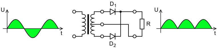
2] An alternator is basically a multi phase AC motor being driven in reverse (like the generator listed above); for it to generate DC current (no matter what the voltage) takes some additional work. Now, for the record, an alternator generates sine wave power; to generate a direct current output, it uses a bridge type rectifier to cut off one half of the sinusoidal current from each leg of the windings; the "DC" current that we measure and use from an alternator comes from the peak of all those sine waves. If you were to look at it's output on an oscilloscope, you would see all of the peak voltage points for the individual windings
on 1/2 of the wave cycle all overlapping, thus generating synthetic "DC" current.
I wish I had the classroom visuals that I had in college; when you see the breakdown on the scope, it really starts to make sense......
Hope this helps...Pat


 Pat
Pat
