Boma 18v 1800w DC

lance

New member
Messages
2
Reaction score
0
Hi y'all.
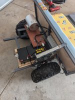
I have seen a thread for the DC Boma 48v 1800w dc control power box setup here on this page, but, I need more assistance than that. The diagram and colour description falls over on like the second line....

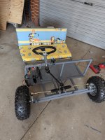
I would really like help with getting it started.. I can't get this bad boy to even turn once, won't start.. sending me bonkers hahaha
It's for the kids and we have spent many hours to get it to this point.

An honest, solid techy that can actually help me would be amazing!! I'll post a couple leads a a time and we get this bugger to run..

Pics attached.
I work FIFO so it will be on and off, but each time we get a switch plugged in I'll post and return for another lead.
 

Attachments

  • PXL_20240906_072529032.jpg
    PXL_20240906_072529032.jpg
    3.6 MB · Views: 7
  • PXL_20240906_072538961.jpg
    PXL_20240906_072538961.jpg
    2.8 MB · Views: 7

Functional Artist

Well-known member
Messages
5,457
Reaction score
3,005
Location
Toledo, Ohio
Howdy & :welcome2:

I installed a 48V 1,800W Boma motor on Damien (years ago)
https://www.diygokarts.com/community/threads/damien.40084/

Do you have a switch connected to the forward/reverse connector?

I didn't at first
...& it drove me nuts :mad2:

Here are the wire definitions, that I came up with :thumbsup:
(see page 7. in the above thread)

Big Power Wires

Battery
: thick Red, thick black
...these are where the Positive (+) & Negative (-) battery cables connect

Motor: thick Yellow, thick Blue, thick Green
...these wires send the "amperage" current from the speed controller to the motor

Small Signal/Control wires

#1 Hall
: thin Red, Black, Yellow, Green & Blue
...these are the signal wires that relay info between the motor & the speed controller

#2 Ignition Switch: thin Red, thin Black
...actually labeled "Power Lock", this is where the key (on/off) switch connects

#3 Throttle: thin Red, thin black, thin green
...this is where the throttle wires connect
...their diagram labels this one as "Speed governor"

#4 Forward & Reverse: thin Yellow, thin Black, thin Gray
...their diagram completely left this one out
…& without a switch connected to this plug, this system will NOT work
(because the controller doesn't know if you want to go forward or backwards)

#5 3-Speed: thin Blue, thin Black, thin Green
...connect an On/Off/On switch here to be able to select low, med or high speed
(if a switch is not connected to this plug the system WILL still operate
...but, it would only operate at medium speed, the "default Mode"

#6 Charge Port: (Red plug) Thin red, thin black
I'm not gonna charge thru the controller
...instead, I connected the charge port (basically) directly to the battery pack

#7 Brake : thin White, thin Orange
...this is where the Brake lever switch wires attach

#8 Brake Light: thin White, thin black
...these wires send current (when the brake lever is activated) to activate "power" the brake lights

#9 Indicator : thin Orange, thin black
...this one seems to be for connecting a Voltage meter

#10 Hour Meter (Black plug) thin Red, Blue. Green, Black
...still researchin' on this one :2guns:
 

lance

New member
Messages
2
Reaction score
0
Howdy & :welcome2:

I installed a 48V 1,800W Boma motor on Damien (years ago)
https://www.diygokarts.com/community/threads/damien.40084/

Do you have a switch connected to the forward/reverse connector?

I didn't at first
...& it drove me nuts :mad2:

Here are the wire definitions, that I came up with :thumbsup:
(see page 7. in the above thread)

Big Power Wires

Battery
: thick Red, thick black
...these are where the Positive (+) & Negative (-) battery cables connect

Motor: thick Yellow, thick Blue, thick Green
...these wires send the "amperage" current from the speed controller to the motor

Small Signal/Control wires

#1 Hall
: thin Red, Black, Yellow, Green & Blue
...these are the signal wires that relay info between the motor & the speed controller

#2 Ignition Switch: thin Red, thin Black
...actually labeled "Power Lock", this is where the key (on/off) switch connects

#3 Throttle: thin Red, thin black, thin green
...this is where the throttle wires connect
...their diagram labels this one as "Speed governor"

#4 Forward & Reverse: thin Yellow, thin Black, thin Gray
...their diagram completely left this one out
…& without a switch connected to this plug, this system will NOT work
(because the controller doesn't know if you want to go forward or backwards)

#5 3-Speed: thin Blue, thin Black, thin Green
...connect an On/Off/On switch here to be able to select low, med or high speed
(if a switch is not connected to this plug the system WILL still operate
...but, it would only operate at medium speed, the "default Mode"

#6 Charge Port: (Red plug) Thin red, thin black
I'm not gonna charge thru the controller
...instead, I connected the charge port (basically) directly to the battery pack

#7 Brake : thin White, thin Orange
...this is where the Brake lever switch wires attach

#8 Brake Light: thin White, thin black
...these wires send current (when the brake lever is activated) to activate "power" the brake lights

#9 Indicator : thin Orange, thin black
...this one seems to be for connecting a Voltage meter

#10 Hour Meter (Black plug) thin Red, Blue. Green, Black
...still researchin' on this one :2guns:
I do have a the three wire (reverse and go forward lever/button)

Got the main positive and negative connected, the 3 main motor wires connected, I feel confident about those, evel the (what they call) hall wires I'm pretty confident about..

God it's annoying, I really thought it would be plug and play grrrr hahahha.

The ignition switch had a female plug on it, that needed to be connected to another female plug.. brand new from eBay whole kit.... So I just spliced the wires together..

I need to take better pics and lay it out. Maybe that will make it easier to help
 
Top