SDCoston
New member
....or just a bunch of washers..
Ha Ha! That's what I did to tighten up my engine at the very last! I know it's not "clean," but it worked great for me.
....or just a bunch of washers..

Suggest using nylock nuts or double nutting the bolts on the pedals and return spring in addition to the Loctite. The vibration on a running cart will be enough to loosen them.
Also, that Harry Homeowner hardware - looks like it is from Ace or HD - is rather soft. Consider replacing them with better hardware that you might scrounge over time.
Do you have a separate throttle return spring directly on the carb linkage? If not, consider adding one for safety.
Edit: I just reread this; it sounds preachy. I do not mean it to be. Just suggestions, that's all.
No problem - I understand what you are saying. I was a bit suprised they worked loose so quickly because I had them cranked down pretty good.
I have Grade 8 bolts and nylock nuts for steering and motor mounts. I used these for initial assembly because I have to take it down again and I didnt want to use the nylock nuts. The pedals came with hardware, but I switched those bolts out for the ones shown for the same reason. The temporary ones on the steering are stainless button head cap screws and ones on the pedals are basic zinc plated hardware and not even the right size - I think they are 1/4 and actual ones are 5/16. I might have to keep the one at the pitman arms because I need a real low profile head to clear the front of the cart. I am thinking of replacing the eye bolt with a weld tab once I get all the throttle and brake lines in place because I'm probably going to weld some keeper tabs on for them anyway.
I do not have the throttle return spring yet, but I plan on adding one.


where did you get your clevis and the pins to hold them on? I think that set-up is really clean. Very nice job, I am enjoying this build.
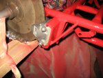
I'm not 100% on the slots in the rotor, but I think they are better served turning in the same direction as the axle.
 Turn your disc around.
The caliper (if I'm looking at this correctly) is also on the wrong side of the axle. The brake rod should be pulling the arm to close the pads.
:What was your thinking behind the position of the caliper? IIWM, I would have the lever on top of the caliper; less chance of "bottom-out" damage...
If he put the lever on top it would have needed to be pushed and it was better/easier to set it up as a pull.
I was thinking at first That JCB had set it up to push the arm instead of pull it. I really don't think bottoming out is an issue at all here, at least not for the caliper.


I worked on the brakes tonight and it looks like they will work! I'm not totally happy with the setup. I hope there is not too much in the way, we'll test it out and see. I used a clevis on each end, linked together with a 1/4" steel rod I cut to length and threaded. Is my rotor correct or should the slots on the rotor follow the direction of rotation? I didn't think about it until I looked at the photo. Still need to weld the bracket.
I'll work on the throttle in the next day or so, I played around with it some tonight and I think I have a plan.
Isn't the caliper supposed to be mounted in a bracket that allows it to "float"? I've never seen one mounted solid.


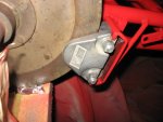
I'm pretty sure you need to float that caliper. As the pads get worn, if the caliper can't move & self-align, you will eventually be using only one side of the brake. Sorry to be the one to tell you that! What does your bracket look like?