Batt-Bridge "Battery Pack Balance Monitor" (wiring diagram & instructions)

Status
Not open for further replies.

Functional Artist

Well-known member
Messages
5,335
Reaction score
2,822
Location
Toledo, Ohio
I used these videos to teach myself how to solder!! They were really good. I soldered up a whole metal detector board from scratch and didn't have one problem

Me too :cheers2:

I could (kinda) solder (roughly)

...these videos, showed me what I was doing right

...& what I was doing wrong :2guns:


* I never heard of the concept of WPI (work piece indicator)

...but, have been practicing it for years :thumbsup:
 

Functional Artist

Well-known member
Messages
5,335
Reaction score
2,822
Location
Toledo, Ohio
Still trying to figure out what my issues are with these Batt-Bridges :ack2:

I have done many, many tests
but, I keep getting inconsistent readings
sometimes it signaled an imbalance @ ~1V imbalance
other times it took like a ~4V imbalance to signal an imbalance.

*If I am going to rely on this to monitor an 2kwH lithium battery pack between my legs, I want consistency :thumbsup:

So, I have double & even triple checked
...that the LED's are positioned & wired correctly
...I ordered & tried ultra bright red LED's

Still getting inconsistency's :smiley_omg:


So, "back to the drawing board"
...when I went back to the Batt-Bridge web site, I noticed that the description & diagram had been changed a little bit.

http://www.sunrise-ev.com/LeesEVs.htm#battbridge

The description used to read:

"The Batt-Bridge is about as simple as you can get; that's why it is so inexpensive. If all you want is an 'idiot' light to say, "Stop driving, your batteries are dead," I can't imagine anything any simpler. You really don't need dozens of ICs and hundreds of components just to light a light.
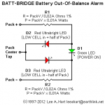
The Batt-Bridge divides the pack in half, and compares the voltage of each half. It lights an LED when one of them is 1v less than the other.

If a cell dies somewhere in the pack, it typically causes a 2 volt change. So the Batt-Bridge warns you that a cell went dead. There are two LEDs, so they indicate which half-pack contains the bad cell.

R1 and R2 are chosen to draw about 10-20ma from the pack. For example, if you have a 120v pack, R1 and R2 each have about 60v across them. At 15ma, they would be R = 60v / 0.015a = 4k ohms. They need to be identical values (1% or hand picked or trimmed). And they must be power resistors; 60v x 0.015a = 0.9 watts, so use at least a 2 watt resistor.

Use an ordinary low brightness green LED. Its purpose is just to indicate that power is on, and to act as a low-voltage 2.4v "zener" diode. However, the red LEDs should be high brightness types -- the brighter the better, so you can see them even in daylight.

Here's how it works. All voltages are relative to the pack center tap. If +pack == -(-pack), then the green LED lights. The green LED's anode is at +1.2v, and its cathode is at -1.4v. The red LEDs don't light because they only have 1.2 volts across them (they need over 1.5v to light).

Now, suppose you have a dead cell in the upper half of the pack. Then +pack is 2v less than -pack. R1 and R2 form a voltage divider, so both ends of the green LED are 1v more negative; its anode is at +0.2v, and its cathode is at -2.4v. This means there is now 2.4v across the lower red LED; so it lights! Likewise, if the dead cell is in the lower half, then the upper red LED lights.

The total resistance of R1 and R2 sets the sensitivity, and the ratio of these resistors sets the desired center-tap voltage of the pack. If both LEDs light, then the resistors are too low a value; increase the resistance of both of them proportionately. Ten milliamps through the resistors is low sensitivity (over 2v difference to light an LED); 20ma is normal sensitivity; 40ma gives you high sensitivity (less than 1v difference to light an LED).

If one LED lights when the half-pack voltages are correct, then adjust the value of one of the resistors. This is also how you deal with packs with an odd number of batteries, where the "center tap" is off by one."

__________________________________________________ ________

Here is the updated version:

"An EV's pack consists of many cells or batteries. In theory, they are all identical. In practice, they aren't. There will always be a "weak link" somewhere in the pack. That's the cell that limits your range, and limits how much you can charge before damage begins.
But it is difficult to know if you have a weak cell. Total pack voltage won't tell you until too late. The amount of circuitry needed to monitor every single cell can get very complicated and expensive!
The Batt-Bridge is a quick-n-dirty "idiot light" to give you a good/bad warning when any cell in the pack goes undervoltage (dead) or overvoltage (overcharged). It works with all types of batteries; lead-acid, lithium, nicad, or nimh. If it lights up red, back off on the current until it goes out. If it stays on even at zero current, stop driving or charging until you find the problem and fix it!

How it works: The Batt-Bridge divides the pack in half, and compares the voltage of each half. When the two halves are equal (within 1 volt or less), a green LED is lit. If a cell goes dead or begins overcharging somewhere in the pack, its voltage typically changes by more than a volt. This imbalance lights one of two bright red LEDs to tell you which half of the pack is low.
D1 is a standard brightness green LED. D2 and D3 should be ultrabright red LEDs for best visibility. R1 and R2 should be identical resistors, chosen to provide about 10ma at your pack voltage. The current sets the sensitivity and brightness of the LEDs."


It looks like the math used to determine the proper resistors needed, depending on the pack voltage, has been changed a bit too.

Here is some testing I have done, gathering data :cheers2:

https://www.youtube.com/watch?v=OnWLNoCSE5I
 

Attachments

  • Batt-Bridge.png
    Batt-Bridge.png
    48.1 KB · Views: 0
  • Batt-Bridge diagram 2018.png
    Batt-Bridge diagram 2018.png
    7.8 KB · Views: 0

Functional Artist

Well-known member
Messages
5,335
Reaction score
2,822
Location
Toledo, Ohio
The first Batt-Bridges I made (going by the original version):
I divided the 48V pack voltage in half. (48V /2 = 24V)
24V / .015 = 1,600 Ohm
24V x .015 = .36 W
(then doubled the wattage to be able to handle the whole pack voltage)

So, I used
...(2) 1.5Kohm 2W 1% resistors (because I already had them)
...(2) standard brightness red LED's
...& (1) standard brightness green LED

But, it didn't seem to work right
So, I made another (this time going "by the book") & used
(2) 1.6Kohm 1W 1% power resistors
(2) ultra bright red LED's
(1) standard green LED

But, it still didn't seem to work right.
...while going over everything, double checking & trying to figure this thing out.
I noticed that that the description has changed, on the web site, a little bit.

Now, it says,
R = packV / 0.02A Ohms 1% (48V / 0.02A = 2,400 Ohm 1%)
P = packV 0.01A Watt (48V x 0.01A = .48W)

* Well huh,
...does this mean that I should have used (2) 2,400Ohm .5W 1% resistors
...instead of the 1,500Ohm 1W 1% resistors?

So, I sent another message to Mr. Hart,
...explaining the issues that I was having & asked if I should be using
...1.6Kohm 1W 1% resistors (according to the old version)
or
...2.4Kohm .5W 1% resistors (according to the the new version)

His response:
"That all sounds correct. What problem are you having?
The LED current is not critical. Anything from 10ma to 20ma is usually
fine, and the resistors can vary over a range of values -- they just
have to be the *same* value.
I would suggest testing your batt-bridge. This is pretty easy if you
have (or can throw together) a small adjustable-voltage power supply.
With your setup, I would use a 24v battery (any kind; it only has to be
able to supply 10-20ma), and an adjustable 24v power supply. Connect the
24v battery and 24v supply in series. Connect the Batt-bridge to it as
if it is your 48v pack.
The green LED should always be on. it just tells you there is power.
When you adjust the 24v supply, you should see

23v - upper red LED on (and green LED)
24v - only the green LED
25v - lower red LED on (and green LED)

The precise threshold where the red LED begins to glow is adjusted by
the choice of LEDs. Picking red LEDs with a higher voltage makes the
+/-1v threshold get bigger. Picking green LEDs with a higher voltage
makes the +/-1v threshold get smaller.
The resistor values basically set the brightness. You want it bright
enough to notice in the daytime; but not so bright that it's painful at
night. You also don't want to use up a lot of battery current
continuously (if the Batt-Bridge is on all the time -- though I think
you were going to use a switch or relay to turn it off when parked?)
Does this help?"

* I thought to myself, Not really,

...it was an "either" - "or" question

...& 800 Ohm's is quite a difference :ack2:
 

Functional Artist

Well-known member
Messages
5,335
Reaction score
2,822
Location
Toledo, Ohio
So, I went at it from a different direction & did some other testing
...like I said earlier but, didn't expand upon :cheers2:

I tested the individual resistors, that I have been using
...800 Ohm, 1.5K Ohm, 1.6K Ohm & even 3K Ohm
...@ 12V, 24V & 48V

Just, to see (for myself) how many milliamps each size was letting thru @ the different voltages

According to my tests
12V
...800 Ohm = 16mA
...1.5K Ohm = 8mA
...1.6K Ohm = 8mA

24V
...800 Ohm = 32mA
...1.5K Ohm = 16mA
...1.6K Ohm = 16mA

48V
...800 Ohm = 63mA
...1.5K Ohm = 32mA
...1.6K Ohm = 32mA
...& 3K Ohm = 17mA

https://www.youtube.com/watch?v=OnWLNoCSE5I

So, it seems, according to my testing that @ 48V
...a 1.6K Ohms resistor lets 32mA thru
...& I believe, extrapolating from the test results, that a 2.4K Ohm resistor would let ~21mA thru

So, they all seem to let more than the recommended 10mA - 20mA thru

* It looks to me that the 3K Ohm resistors, letting 17mA thru, are the only ones that put us in the recommended range :thumbsup:
.
 

Functional Artist

Well-known member
Messages
5,335
Reaction score
2,822
Location
Toledo, Ohio
I also noticed that the new version does not mention that each of the resistors are monitoring only 1/2 of the battery pack voltage

So, if I use 1/2 pack voltage...like the "old version"
...& the math ...from the "new version"

Like this,
R = 1/2 PackV / 0.02A Ohm's 1%
P = PackV x 0.01A Watts

So, for a 48V battery pack that would be,
48V/2 = 24V
24V/ 0.02 = 1,200 Ohm's
48V x 0.01 = 0.48W @ 1%

Now,
...it looks like I should have used 1.2Kohm .5W 1% resistors

* Well, lets go at this from yet, another direction

I went ahead & ordered a couple of Batt-Bridge kits
...right from Mr. Lee Hart http://www.sunrise-ev.com/LeesEVs.htm#battbridge
...we'll see what size resistors he sends me
 

Functional Artist

Well-known member
Messages
5,335
Reaction score
2,822
Location
Toledo, Ohio
Batt-Bridge Update

It's been over (2) months now & I still have not received the Batt-Bridge kits that I ordered from Mr. Hart

I have sent him a few friendly reminder emails
...the first couple he responded (sorry, been busy & such)
...now, he don't even respond :ack2:

I'm starting to think that these things DON'T really work
...or don't work that well (in the real world)

From what I understand, it was originally designed for monitoring lead acid batteries
...which is all that I am trying to do right now

But, the main reason I was interested in the concept was to monitor the balance of Lithium battery packs

So, if it don't work on lead acid batteries
...I'm sure NOT gonna trust it to monitor a 2Kwh lithium pack (on a motorcycle, between my legs)


Now, I'm thinkin' why not just use (2) volt meters :idea2:
...(1) monitoring the left 1/2 of the battery pack
...& the other (1) monitoring the right 1/2 of the battery pack

For example, on a 48V battery pack
...(1) meter should read 24V
...& the other meter should show 24V also

Then, if the battery pack goes out of balance (for any reason) the operator could easily see a variation in between the (2) meters
...while in use
...or as a quick "double check" before charging :2guns:
 

mckutzy

Well-known member
Messages
8,353
Reaction score
108
Location
bc, canada
Why not a 3 position switch,(a dpdt I think it is?) on-off-on(batt 1-off-batt 2) with one meter... select left or right for that batt.
 

Functional Artist

Well-known member
Messages
5,335
Reaction score
2,822
Location
Toledo, Ohio
Why not a 3 position switch,(a dpdt I think it is?) on-off-on(batt 1-off-batt 2) with one meter... select left or right for that batt.

Yup! I like the idea :thumbsup:
...kinda like a "Cycle Analist" I think they call it

One screen or read out
...& a button to cycle thru the different systems

But, thinkin' it thru it seems kinda DIY difficult
...not as simple as just a switch

Remember, I am NOT an expert but, I believe, to get a voltage reading you need a positive (+) & a negative (-) connection

So, we would need a switch (or other circuitry) to connect or disconnect both the positive (+) & the negative (-) connections for the left half of the battery pack
...& then, connect or disconnect both the positive (+) & the negative (-) for the right half of the battery pack

Plus, the operator would need to "deal with it" more like
...putting thought in to it for pushing buttons
...thinking about which side of the battery pack the meter is reading (at this time)
...remembering that reading
...switching to the other
...& then, "mentally" comparing the (2) readings


You don't like the (2) meter idea?
...their only like $15.00 each
https://www.ebay.com/itm/291152585319?rmvSB=true

It seems like it/they
...would be very simple to hook up
...would not require the operator to take their hands "off the wheel" to use it
...& the info would always be "right there" readily available :cheers2:


Here is info on the meter I'm talkin' about http://www.diygokarts.com/vb/showthread.php?t=38583
 

Functional Artist

Well-known member
Messages
5,335
Reaction score
2,822
Location
Toledo, Ohio
:censored: that stupid "idiot light"

Movin' right along :auto:
&
Steppin' it up a notch :2guns:

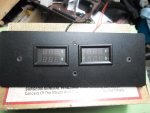
Got the Digital (dual-readout) Battery Pack Balance Monitor about 1/2 done :thumbsup:

I didn't add an on/off switch to this one
...it's gonna be wired direct
...just for test purposes :cheers2:
 

Attachments

  • SAM_9860.jpg
    SAM_9860.jpg
    253.4 KB · Views: 0
  • SAM_9859.jpg
    SAM_9859.jpg
    318.2 KB · Views: 0
Status
Not open for further replies.
Top