brendonv
New member
very nice build.

")

nice you got a way bigger project than me and your way ahed, of course im messing with my plans a ton and am only 13
 . as you know im building the scorpion. my plan right now is to have great aceleration/hillclimbing/rubber burning and max out at about 45mph, i calculated if iwanted to i could get acceleration of an average crt and reach about 70 to 0 mph without taking off the gov theres a reason why i bought a tc!
Hello Grizz,
Have you put the front on hold for right now?
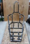
I am curious, did you have any issues (even small ones) with the main frame part of the build?
BTW, ... thanks for the post over at spidercarts to the designer!
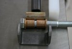
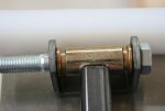
 You can see in my pictures I used the base of an old shipping container. I drew lines at right angles to each other to line up with the frame section. I clamped it down and tack welded everything to make sure it stayed true and line up. If I were to do it again, I would use a thicker piece of hardboard at least 1" to make sure it was flat.
Hello Grizz,
I am curious, did you have any issues (even small ones) with the main frame part of the build?
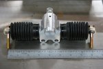
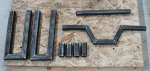
Since you have your pieces cut, could you please mock fit them together with the spindle mounts and see if your rack ends are inline with the A-arm pivot point?
I just checked and I get 7 5/8 center to center on the pivot points on the A-arm versus 8' on the rack, so the rack is over 3/8 of an inch. I your case, you must be over 5/8 is that correct? I don't understand why they have to line up, but the simplest solution would be to modify SB05-30 and SB5-45 by increasing length 50 5 3/8 or 5 5/8 in your case and then would we need to reduce AA08-90 and AA4.5-90 by an equal amount to keep track width the same. I have to read more on this "bump steer" to make a decision on this one.
Grizz,
I don't think you need to change the AA parts for .375", I would think you can adjust for that in the Heim Joints.

Grizz,
Everything is good to go. With the guidance of Theo and The Machine, the front end mechanics work and theirs no bumpsteer!
Thanks Guy's
Bill