anyone made a push button turbo?

Status
Not open for further replies.

dcastillo

New member
Messages
319
Reaction score
0
Location
Tampa Florida, USA
just had this thought earlier today, Im sure someone here has done it so I wanted to get some opinions (how well it works or if its bad for the electric setup)

basically, assuming you have a 36V motor...
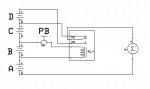
you connect 3 12v batteries as usual, but the last battery, instead of going to the controller, goes to the common of a 12V contact (controlled by a momentary pushbutton), the NC side goes to the controller, the NO side goes to another 12V battery and then to the controller....
hence, when you press the button it instantly adds the 4th battery in series giving you 48V while you hold the button...

in theory I think it would work, but I dont know a lot about how controllers operate and if they would have a problem with this setup..

Thought????
 

itsid

Moderator
Staff member
Messages
11,563
Reaction score
246
Location
Ruhrpott [Germany]
I'm sorry, I think I don't understand how you want to connect the fourth battery.

I can't exactly see how to add a fourth battery in series with just a push button.

Assuming the following txt-schematics
[motor_terminal A] - [Powercontroller] - [motor_terminal B]
And
[Powercontroller] - [Bat1-] [Bat1+] - [Bat2-] [Bat2+] - [Bat3-] [Bat3+] - [Powercontroller]
(all the same Powercontroller)
If you want to add a fourth battery in series, you must have at least two connections for it,
[Bat3+] -here- [Bat4-][Bat4+] -and here- [Powercontroller]
at the same time you need to cut the connection between Bat3+ and the Powercontroller
So three contacts, one could be permanent ([Bat3+]-[Bat4-]) I think,
In any way the pushbutton has to withstand quite alot of current,
so I doubt that is a very good idea.

*shrugs*

Could you draw a schematic how you intend to connect the batteries, controller and motor?
Maybe I just miss something in your description.

'sid

PS I think there are controllers that can do something like this much more convenient and reliable ;)
 

dcastillo

New member
Messages
319
Reaction score
0
Location
Tampa Florida, USA
hows this...
since I dont really know much about controllers, I left it out of the pic
under normal conditions, batteries a,b,c power the motor, once you press the button PB, it removes the pos connection to the third battery and moves it to the fourth battery...
 

Attachments

  • turbo button.JPG
    turbo button.JPG
    45.6 KB · Views: 7

itsid

Moderator
Staff member
Messages
11,563
Reaction score
246
Location
Ruhrpott [Germany]
Ah.. relay...

Yes, that would work I guess, if instead of the Motor you add the power input of the controller and the motor just to the power output of the controller (as usual).

As long as the controller does not have a voltage regulator.
I've never tested such set up nor seen anything like that, so maybe you want to wait a little for a more educated opinion than mine ;)

'sid
 

ed1380

Banned
Messages
1,182
Reaction score
1
Location
ATL, GA
That sounds pretty neat especially if your speed controller can only handle 36v and you have a brushed motor. Just wire in a diode capable of the amps at the output of the ESC and it'll work.
 

dcastillo

New member
Messages
319
Reaction score
0
Location
Tampa Florida, USA
That sounds pretty neat especially if your speed controller can only handle 36v and you have a brushed motor. Just wire in a diode capable of the amps at the output of the ESC and it'll work.

so your thinking of adding the 4th battery after the controller?
Is the diode to protect back EMF when the motor cuts off, so it doesnt damage the controller?


I was actually thinking of putting it before the controller (assuming the controller is rated at 48V)
 

ed1380

Banned
Messages
1,182
Reaction score
1
Location
ATL, GA
We are talking about a real controller here. Not a relay. Correct?

Think about it this way. The controller is designed to handle 36v out. Once you give the motors 48v, the wires connecting the motor to the ESC will also be at 48v, hence the diodes preventing the 48v reaching the ESC. Only problem is that the ESC will not be able to have reverse with the diodes connected
 

ed1380

Banned
Messages
1,182
Reaction score
1
Location
ATL, GA
Well I just solved it. Run in through a DPDT switch like the diagram. In the left(normal) position the ESC is connected to the motor and the 48v is open. When flipped to the right, the ESC is disconnected from the motor and 48v is supplied to the motor. Definitely get a switch that is rated for the full power. I also recommend a switch that defaults to one position and momentary to the other position.

 
Status
Not open for further replies.
Top