Another live axle conversion

Status
Not open for further replies.

Hellion

Moderator
Messages
8,393
Reaction score
3,533
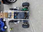
Hellion - the only original picture I have before modifications is the one posted above. I'll see if the guy I got it from has any still.

The only pics visible in this thread are the ones where you're working on it and in pieces. You may be able to see them, but I cannot. I see the icon for a broken picture link in post #7, but that's it.

All your photo-hosting site photos may eventually go poof as they invariably do over time but when uploaded to this site, will exist here forever...
 

SpiderSpartan

New member
Messages
94
Reaction score
0
Location
Cincinnati, Ohio
Also here is a pic of similar bearing mounts you may want to think about adding this support.

Thanks, I will add some bracing to my hangers.

I figured out the solution to my next problem today. I got a couple of these weasler hubs from my local tractor supply.

http://www.tractorsupply.com/tsc/product/weasler-hub-x-series-round-1-in-bore-with-keyway-set-screws?cm_vc=-10005


They're reasonably priced and locally available. The problem is they have 2 sections, one 2 inches and the other 2 1/4 inches. The sprocket and brake drum that were on the kart have 2 1/8 inch center hole. I figured out that 2 inch copper pipe would perfectly fill this gap.Of course my local stores only sell 2 inch copper pipe in 10 foot sections for $65:smiley_omg:

Turns out I had some bailing wire on hand that worked out pretty well too. Just had to form it into a tight ring around the 2 inch section and work the sprocket around that.
 

Attachments

  • 20160723_204022.jpg
    20160723_204022.jpg
    397.1 KB · Views: 3
  • 20160723_204001.jpg
    20160723_204001.jpg
    312.3 KB · Views: 4
  • 20160723_203943.jpg
    20160723_203943.jpg
    506 KB · Views: 6

SpiderSpartan

New member
Messages
94
Reaction score
0
Location
Cincinnati, Ohio
So close, yet so far away.

  1. welded the sprocket and brake drum to their hubs
  2. cut the original axle for the new sprocket position
  3. drilled out the engine mount and mounted the engine

Now I've noticed the torque converter back plate has fins on it that are going to interfere with the chain route. I'll look at rotating the plate, but I might have to go with a jack shaft.
 

Attachments

  • 20160724_190011.jpg
    20160724_190011.jpg
    376.7 KB · Views: 21

Denny

Canned Monster
Messages
11,582
Reaction score
8,008
Location
Mayberry, Indiana
Nope, with a wood router and wood bits you can trim the fins for clearance. You can also use a die grinder or a file. With all of these methods though use plenty of PB Blaster as a lubricant so the aluminum does not plug up the cutting edges. :thumbsup:


Denny
 

Jfive

New member
Messages
645
Reaction score
1
Location
Great falls Montana
I made a jackshaft for two reason, this being one. Allows me to have the engine back for better clearance and I changed the drive ratio to the more favorable 1:6.277. Not sure how your wanting the jackshaft but jackshaft johnny on YouTube has some neat ideas
 

SpiderSpartan

New member
Messages
94
Reaction score
0
Location
Cincinnati, Ohio
My first thought was to grind a path for the chain with the angle grinder. I'm afraid the path is too close to the drive pulley though. I also wasn't sure if the fins were designed in for structural support and with an oversized engine I don't want to risk the back plate failing. Any way, Jack shaft kit and chain should be here before the end of the week.
 

SpiderSpartan

New member
Messages
94
Reaction score
0
Location
Cincinnati, Ohio
After a week out of town for work and a weekend being sick as a dog I'm finally back at it. :wai:

Got the jackshaft mounted and chains cut to length tonight. I had to cut a channel in one of my re-enforcements for the chain, so I plan on welding another piece to bridge the back side of that channel. Next:
  1. Align and tighten everything on the axle and jackshaft
  2. re-mount the brake band
  3. Connect the throttle, electronics, and gas tank
 

Attachments

  • 20160802_204554.jpg
    20160802_204554.jpg
    390.3 KB · Views: 13
  • 20160802_204621.jpg
    20160802_204621.jpg
    275.3 KB · Views: 9

SpiderSpartan

New member
Messages
94
Reaction score
0
Location
Cincinnati, Ohio
Today I mounted the brake band in its new location, cleaned up some welds, and lined everything up on the axle and jackshaft. Got it done so late I didn't even run it.
 

Attachments

  • 20160803_203301.jpg
    20160803_203301.jpg
    404 KB · Views: 6
  • 20160803_185110.jpg
    20160803_185110.jpg
    375.4 KB · Views: 7
  • 20160803_185123.jpg
    20160803_185123.jpg
    324.4 KB · Views: 8

chancer

ɔ ɥ ɐ u ɔ ǝ ɹ
Messages
9,358
Reaction score
83
Location
COMFORT, TEXAS
Looking good. On your first test drive(s) dont trust that brake. Sometimes they tend to slip sideways off the drum and need some adjustment. Especially when just added by guys like us. Good to know.
 

SpiderSpartan

New member
Messages
94
Reaction score
0
Location
Cincinnati, Ohio
Looking good. On your first test drive(s) dont trust that brake. Sometimes they tend to slip sideways off the drum and need some adjustment. Especially when just added by guys like us. Good to know.

Thanks. The thought of that had crossed my mind. I'll run it on the jack stand a little before a few gentle laps around the yard.
 

MrC.

Member
Messages
238
Reaction score
0
Location
florida
Take a few steps back and get us a picture of the whole dang thing!

Looking good
MrC.
 

SpiderSpartan

New member
Messages
94
Reaction score
0
Location
Cincinnati, Ohio
Started it up on the jack stand this morning and it's looking good. Still need to connect the throttle, gas tank, electronics, and figure out how to control the choke. Here's a wider shot of the back. The front is loaded up with tools and random pieces. It's also still hooked up to the hoist. I'll get some overall shots once it's all cleaned up and put together.

https://youtu.be/co4O18CMyS0
 

Attachments

  • 20160804_091653.jpg
    20160804_091653.jpg
    757.9 KB · Views: 12
  • 20160804_091706.jpg
    20160804_091706.jpg
    777.3 KB · Views: 11

SpiderSpartan

New member
Messages
94
Reaction score
0
Location
Cincinnati, Ohio
Finally got it out for a test drive. I have a couple issues to work out.

First, I'm not getting the full throttle range with my throttle cable. It moves, but it's not going anywhere fast. With 10 teeth on the tav driven and both jackshaft sprockets, 54 teeth on the axle, and 13" wheels I should be getting up to about 25 mph at full throttle. I'd be lucky to get up to 5 mph right now.

Next, the brake band feels kind of loose. I never got fast enough to really test it though.

Once I get the electronics connected I'll be able to start it and test much easier. Right now I have to hot wire it to get it started. Here's a few shots of the whole thing.
 

Attachments

  • 20160804_153941.jpg
    20160804_153941.jpg
    642.2 KB · Views: 8
  • 20160804_153952.jpg
    20160804_153952.jpg
    576.6 KB · Views: 14
  • 20160804_153959.jpg
    20160804_153959.jpg
    589.1 KB · Views: 11

chancer

ɔ ɥ ɐ u ɔ ǝ ɹ
Messages
9,358
Reaction score
83
Location
COMFORT, TEXAS
Careful running it too much at partial throttle, The clutch may not fully lock and cause it to slip and burn the clutch shoes.
 

MrC.

Member
Messages
238
Reaction score
0
Location
florida
It must be slipping with that engine and 5.4 to 1 gear and those small tires it should haul butt. Easiest thing to change is the 10 tooth sprocket to 9 or 8 that should wake it up. But top in with your current gearing should fly.Looking good.

MrC.
 

SpiderSpartan

New member
Messages
94
Reaction score
0
Location
Cincinnati, Ohio
Got everything wired up tonight, but I'm running into a couple electrical problems.

First, the starter for this engine has an engage solenoid, instead of the spring loaded ones I'm used to. If this solenoid is not engaged when the starter tries to crank, it just free spins. Maybe I could put a capacitor delay circuit to the to external solenoid to delay it from engaging until the internal solenoid is triggered. Any other suggestions?

Next, when I stop pushing the key to the start position the starter keeps spinning. The only way I could stop it was to pull the wires off the negative battery terminal. I'm thinking of adding a 2K Ohm pull down resister from the solenoid to ground.
 

Attachments

  • Thunderkart Wiring.jpg
    Thunderkart Wiring.jpg
    55 KB · Views: 1

SpiderSpartan

New member
Messages
94
Reaction score
0
Location
Cincinnati, Ohio
After some more thought I think I'll try to rewire it like this before digging into a more complicated delay circuit. I'd appreciate any suggestions though.
 

Attachments

  • 20160806_092541.jpg
    20160806_092541.jpg
    103.9 KB · Views: 1

SpiderSpartan

New member
Messages
94
Reaction score
0
Location
Cincinnati, Ohio
Once again, :mad2: 
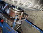
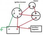
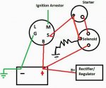
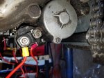
I got to thinking about the starter and the fact that there were 3 pegs on it. As it turns out, 1 solenoid/relay, 1 positive switch, and 1 ground. I had connected to the ground lug instead of the positive switch lug. As long as I powered the solenoid before the motor, and removed the connections after it started, it worked this way. Now that I've hooked it up correctly it works great. Now to adjust the throttle.
 

Attachments

  • 20160806_144459.jpg
    20160806_144459.jpg
    441.7 KB · Views: 3
Status
Not open for further replies.
Top