Another Arachnic Granddaddy Iteration - Project Log

fuzzy

New member
Messages
12
Reaction score
23
I have been watching the DYGK forums for a while trying to learn as much as possible from all the different types of projects everyone has going. It has been very helpful.

We finally got the project up running on its own power about a month ago and have been tuning on bugs, so I'm finally ready to post. I'm not much of a social media person, but hope someone will find helpful tips scattered throughout.

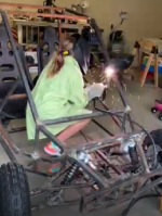
My neighbors have joked that this has been autoshop for my daughters. They helped measure, mark, chop, grind, weld, sand, paint, bolt on most aspects.

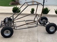
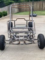
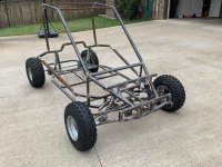
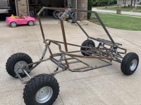
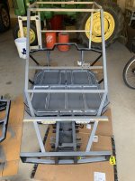
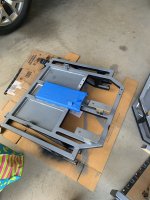
Using the Arachnid plans, I stretched/widened both frames about 6" to accommodate adults. Also widened/heightened the front suspension box to account for the rack and pinion width to make eliminating bump steer easier, and have a better kingpin layout. Plan was to fit the two racing seats on sliders with a space between for parking brake. Wanted to use the Predator 420, so with that amount of power I felt like needed a little beefier suspension. That got us to widening the suspension and 20" tires.

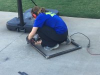
Started with walking the girls through the plans to mark the extensions on frame drawings and then translate the marks to the pertinent parts cut sheets.
Rear frame was easiest to start fabrication. Funny how their personalities come out in using the tools. The type A older one barely pushes the chop saw hard enough throw sparks, the middle outgoing daughter bogs the saw down.
thumbnail_IMG_5259.jpg

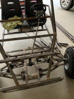
Built the back frame and only lower portion of main frame first. Wasn't convinced on layout of roll cage portion.

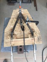
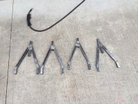
Then built a jig for the A-arms so they would be as close dimensionally as needed, and kept the jig in event a replacement is needed. The A-arm dimensions were enlarged a couple inches in length and spacing of attach points to handle the added loads.
thumbnail_IMG_5686.jpgthumbnail_IMG_5688.jpgthumbnail_IMG_5690.jpg

Where the heim joint attaches at the kingpin, I used a weld-in bung that has four plug welds and welded all around on the end. This is instead of the welded on nut in the plans.

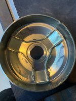
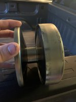
One of the complications I added was not using the tractor links for the attach points. I felt these were inadequate for the setup, so I looked for a bushing layout and ended up recreating the wheel. I wanted to use 5/8 bolts. On the suspension block are welded tabs from 1/4" x 2" bar stock. On the A-arms is welded a piece of 2" pipe. We then poured polyurethane bushings. I looked at milling them from PU round bar stock, but it is difficult to mill.

If I were to do this again, I would not use the pipe and my own bushings. Great learn for the kids, and myself, but took way too long. These same items can be bought fairly inexpensively that thread into a welded bung.

thumbnail_IMG_6222.jpg

Front hubs are the typical trailer hubs, found a kit on sale that had axle, hub, and bearings for about $35 each kit. Vertical section is a piece of DOM, beveled at both ends, cut the hub axle to fit. I think the hub is about 5 degrees off perpendicular to the king pin. King pins are inclined about 8 degrees using the rake of the A-arm placement. Tie-rods are attached to a tab welded to the king ping just below the hub. Ended up with a 10" total travel without using the heim joint extenders.

thumbnail_IMG_6394.jpg

Will continue in second post.
 

fuzzy

New member
Messages
12
Reaction score
23
Rear frame is connected to main using two 3/4" bolts. Same bar stock tab configuration as front suspension. Should note I placed gussets on rear tabs of front suspension and on all rear end tabs. Tried to space rear end attachments as far apart as possible for lateral loads (thinking of all the doughnuts in its future).

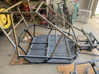
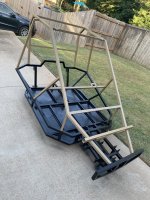
Took a lot of tacking and rearrangement to finally get a roll cage outline that we like to look we liked, gave support where needed, and had access.

thumbnail_IMG_6746.jpgthumbnail_IMG_6748.jpgthumbnail_IMG_6749.jpgthumbnail_IMG_6751.jpg
Ended up with a small bull bar on front, windshield area ended up as a rectangle so we could get a vertical member. Later addition sees a bar coming up at your shoulder to keep you further away from the ground in event of a rollover.

Main framing is done, then was time to start adding the main components.

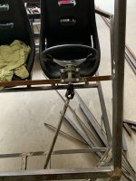
Rack and pinion was one of the cheap sets on that direct from China site. Held on by replacing the two bolts on body and attaching to a plate, plus welding on two split collars near its end.

In same steering package came the steering wheel and shaft. Cut shaft in two and extended using round bar. Mounted steering wheel on two cheap pillow blocks.

Bought hydraulic brake package from same site. Only using the large disc on the axle. Had to rotate the master cylinder to get it in a place it would not get knocked off or hit with rocks. So rotated to right and made a bell and crank setup to change the motion. For the final weight, I can't lock up the back wheels on pavement with this arrangement, but does stop pretty well.

welding.PNGthumbnail_IMG_7254.jpgthumbnail_IMG_7255.jpgthumbnail_IMG_8322.jpg

Don't have any picks of work while reinforcement was getting added, but can see it later.

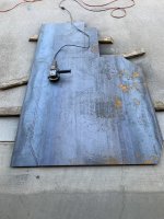
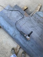
After all frame work and ancillary was added, I wanted to skid the bottom fairly liberally in case they ran up on a tree stump or debris. Used a sheet of 14 gauge.

thumbnail_IMG_8918.jpgthumbnail_IMG_8920.jpg

Sat the kart on the sheet, outlined with a marker, removed kart, and remarked just inside. This gave room for the tacks.

In prep for welding, using a flap wheel I prepped the weld areas and then sprayed with weld thru primer. Did same for bottom of kart.

Out of pic room, so on to next post.
 

fuzzy

New member
Messages
12
Reaction score
23
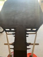
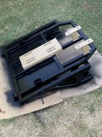
Got the skid plates welded on, tacks along outside edge on bottom and multiple 1" welds inside each panel area. Wanted to be able to stand on it.

This is where I got to one of the most tedious lessons learned, paint prep. This is a conundrum due to amount of time we all really have to spend on a project. If I could fab quickly, I would just clean each stick of tube when it came in with a flap disc and then work. But, that is not reality, so I waited until now. What a pain.

We built a temp blast booth in a bay of the garage. Hung plastic sheeting up on garage track, extended with PVC pipe, laid a piece across the top, and put a box fan in the window of the bay. Ended up connecting two compressors to get enough CFM.

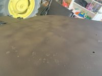
Once blasted, primed 2 coats using the self etching from HF. First top coat was applied to the bottom of skid plate so we didn't have to flip multiple times. Used the rubberized coating from HF.

thumbnail_IMG_9848.jpgthumbnail_IMG_9851.jpgthumbnail_IMG_9852.jpg

Because I am a nerd, we used AC Delco body sealant along all inside edges of skid plate to tubing.

thumbnail_IMG_9853.jpgthumbnail_IMG_9854.jpgthumbnail_IMG_9855.jpg

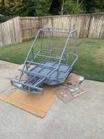
The girls wanted a two-tone scheme, so semi gloss black on bottom and something akin FDE on top.


thumbnail_IMG_9856.jpgthumbnail_IMG_9857.jpg
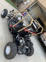
You can see from the rear end I have gone with a jackshaft setup. Chose this since we eventually plan to mod the engine and didn't trust the all-in-one plate.
 

fuzzy

New member
Messages
12
Reaction score
23
Final product and lessons learned post.

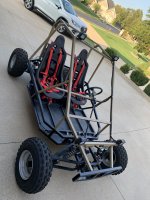
thumbnail_IMG_9918.jpgthumbnail_IMG_9919.jpg
-Using electric start, running a lawnmower battery, and 4 LED lights (2 flood, 2 spot, 18 Watts each)
-5-point harnesses with lap belts bolted to frame using 1/2" grade 8, straps are tied off to back bar per directions.
-Chinese copy of Comet 40, replaced belt to be Comet original.
-#40 Chain, 10 tooth on jackshaft, 60 tooth on axle
-Axle is 1 1/4" chrome moly tube
-Added second set of bearings nearer the wheels, was afraid of bending the axle
-Shaft collar on in/out of everything, plus snap ring on end of axles.
-Relocated key to between seats, along with parking brake. 4 switch box controls the lights.


-Reduced idle on the engine to get rpms about 1,450 when first started, but still wanted to try to move.
-First runs were great, but was an issue starting and stopping due to belt grabbing. Saw driver was not fully disengaging unless you hit it with channel locks (tool of choice for this item).
-Would easily slide rear end on pavement, top speed about 30 (using Waze on phone)
-Rear shocks bottomed out pretty easily.
-Was still really fun in the dirt, girls then understood what it was really for.

Since first runs we have changed to lighter weights and red springs in the driver. Upon disassembly, found the outside cover portion had jumped off the weights. There was basically no dry lube anywhere. We polished her up, lubed the crap out of it and reassembled. Now it fully disengages and you can see the bushing.
cvt internal.jpgrebuilt.jpg

Also changed the rear shocks to the fake reservoir type that are on the front.
Flipped the bell and crank on the brakes so I have more leverage.
Set the idle back to about 1,750 rpm and re-attached the throttle cable to get its max rpm. It is hitting about 4,100.

Took her out last night with all the mods. Completely different animal.
-Sits still on idle, either starting or when rolling to a stop. That safety issue is eliminated.
-Lots more torque on engagement because where it is now on the power band.
-Top speed is much higher (not measured yet). Was to a point that wheel balance is now an issue. I caught up to a neighbor driving up the hill.

Also proved it will do doughnuts on dry pavement at entrance to the neighborhood.

That was great until the battery slid, hold down stud contacted hot wire to starter and caught the trap on fire. Once extinguished she started right up and continued. Additional lesson, add onboard fire extinguisher.

I wish there was another 1" or 2" from my head to top of cage. Not an issue for the girls.
Will add rack to back for small tool box.
Not happy with throttle cable to pedal arrangement, but small mod is all that is needed.
Plan to add mount points for hunting platform on top.
Will likely switch axle sprocket to 72 tooth, if we mod and increase engine rpm it might get a little fast.
 

TNThomas

Well-known member
Messages
387
Reaction score
370
Location
Washington
I have been watching the DYGK forums for a while trying to learn as much as possible from all the different types of projects everyone has going. It has been very helpful.

We finally got the project up running on its own power about a month ago and have been tuning on bugs, so I'm finally ready to post. I'm not much of a social media person, but hope someone will find helpful tips scattered throughout.

My neighbors have joked that this has been autoshop for my daughters. They helped measure, mark, chop, grind, weld, sand, paint, bolt on most aspects.

Using the Arachnid plans, I stretched/widened both frames about 6" to accommodate adults. Also widened/heightened the front suspension box to account for the rack and pinion width to make eliminating bump steer easier, and have a better kingpin layout. Plan was to fit the two racing seats on sliders with a space between for parking brake. Wanted to use the Predator 420, so with that amount of power I felt like needed a little beefier suspension. That got us to widening the suspension and 20" tires.

Started with walking the girls through the plans to mark the extensions on frame drawings and then translate the marks to the pertinent parts cut sheets.
Rear frame was easiest to start fabrication. Funny how their personalities come out in using the tools. The type A older one barely pushes the chop saw hard enough throw sparks, the middle outgoing daughter bogs the saw down.
View attachment 142682

Built the back frame and only lower portion of main frame first. Wasn't convinced on layout of roll cage portion.

Then built a jig for the A-arms so they would be as close dimensionally as needed, and kept the jig in event a replacement is needed. The A-arm dimensions were enlarged a couple inches in length and spacing of attach points to handle the added loads.
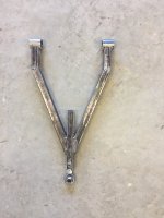
View attachment 142683View attachment 142684View attachment 142685

Where the heim joint attaches at the kingpin, I used a weld-in bung that has four plug welds and welded all around on the end. This is instead of the welded on nut in the plans.

One of the complications I added was not using the tractor links for the attach points. I felt these were inadequate for the setup, so I looked for a bushing layout and ended up recreating the wheel. I wanted to use 5/8 bolts. On the suspension block are welded tabs from 1/4" x 2" bar stock. On the A-arms is welded a piece of 2" pipe. We then poured polyurethane bushings. I looked at milling them from PU round bar stock, but it is difficult to mill.

If I were to do this again, I would not use the pipe and my own bushings. Great learn for the kids, and myself, but took way too long. These same items can be bought fairly inexpensively that thread into a welded bung.
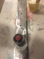
View attachment 142686

Front hubs are the typical trailer hubs, found a kit on sale that had axle, hub, and bearings for about $35 each kit. Vertical section is a piece of DOM, beveled at both ends, cut the hub axle to fit. I think the hub is about 5 degrees off perpendicular to the king pin. King pins are inclined about 8 degrees using the rake of the A-arm placement. Tie-rods are attached to a tab welded to the king ping just below the hub. Ended up with a 10" total travel without using the heim joint extenders.
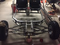
View attachment 142687

Will continue in second post.
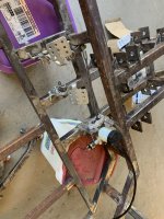
You sent me info on the hubs a few years back and that is exactly the way I went, Its a great sturdy and cheap way to go about building it. I also got quite a few ideas from your initial front frame build with your shock/bumper setup, thanks again! Your build looks great, lots of good info on here. You could always chop the top off, and add in Spacers a few inches long. I had to do that twice on my A-arms.
 
Top