Advanced Hemi 212cc Predator Build

Status
Not open for further replies.

bob58o

SuckSqueezeBangBlow
Messages
9,646
Reaction score
1,846
Location
Chicago-town USA
I continue to dig because I want to be prepared as much as possible...

Welch Plug Holes!! What are those??? What do they do??? Which one does what??? I don't know??? Its like the G-Spot. {shrugs} lol
Perhaps the Holy Grail concerning the tuning of this carb. Still going to research different style E-tubes as well.

While being very lazy and considering "Getting My Head Looked At," I was eyeballing the 160cc snow slinger. Global Warming is real, right????? lol

Research is moving towards Welch Plugs and E Tubes.
 

Poboy kartman

Senior Moments Member
Messages
12,461
Reaction score
66
Location
White Settlement Texas
Welch plugs are those round aluminum circles pressed into the carb body that cover something up.

DIY stickers are those blue and orange circles that AUGMENT my sexy body....and Everyone wants to see and can't get enough of!
 

bob58o

SuckSqueezeBangBlow
Messages
9,646
Reaction score
1,846
Location
Chicago-town USA
Welch plugs are those round aluminum circles pressed into the carb body that cover something up.

Apparently Holes. :surrender::lolgoku:

---------- Post added at 06:02 PM ---------- Previous post was at 06:00 PM ----------

DIYGK Stickers are those round Blue and Orange circles pressed onto my Sexy body that cover something up.

Fixed that for ya!!!:roflol:
 

bob58o

SuckSqueezeBangBlow
Messages
9,646
Reaction score
1,846
Location
Chicago-town USA
Rotfl!!!!

---------- Post added at 06:25 PM ---------- Previous post was at 06:04 PM ----------

And O-Ring Mods. I'll let you guys know if the Pilot has both top and bottom O-rings or if this does not apply for this Big Dint Carb.
 

cavfire

Member
Messages
110
Reaction score
1
Location
auburn, georgia
I continue to dig because I want to be prepared as much as possible...

Welch Plug Holes!! What are those??? What do they do??? Which one does what??? I don't know??? Its like the G-Spot. {shrugs} lol
Perhaps the Holy Grail concerning the tuning of this carb. Still going to research different style E-tubes as well.

While being very lazy and considering "Getting My Head Looked At," I was eyeballing the 160cc snow slinger. Global Warming is real, right????? lol

Research is moving towards Welch Plugs and E Tubes.

Just to the right of the idle mixture screw there's a welch plug, pop that off and there are four little holes. They can be opened up some, but not much. There isn't a whole lot of meat on that bone before having to throw the carb in the trash or trying to solder the holes back up. Not something I'd try on gas on a yard kart, maybe methanol racing kart.

Awesome video, that long wheelbase is a bear in tight spots.
 

bob58o

SuckSqueezeBangBlow
Messages
9,646
Reaction score
1,846
Location
Chicago-town USA
Some good info here that I stole from the internet....

Regarding E-Tubes and how they work...

"Why didn't you ask a simple question?

In the thread “750 Holley carb help” Klaus made this statement, “On carbs it's very important that the correct two-phase flow gets established during emulsion. Otherwise you will see RPM dependency of AFR.” Thank you Klaus, but forgive me if I see your remark as a profound understatement. Incorrect two-phase flow is at the root of all this aggravation. People who have drill bits but don’t know why to use them have been molesting innocent carburetors for a long time. Now some of them are in charge of the manufacture of new carbs and they think they have improved them by using larger drill bits to make the air bleed and “emulsion” orifices. I guess the guys that engineered the original carburetors on the old muscle cars were pretty stupid or they would have “improved the emulsion” 40 or 50 years ago when they had their chance. After all, they had the awesome power of the single-point ignition system at their disposal, they shouldn’t have been afraid of a little soot.

It is well documented that introducing air into the main well encourages low signal flow and can encourage or discourage high signal flow. The natural characteristic of a plain jet and nozzle (no air) is to get richer as airflow increases. The purpose of the air bleed system is to modify that behavior to accomplish a constant (or the desired) air/fuel ratio over as wide a range of airflows as possible. The particular ratios for power and cruise are realized by the selection of jet and rod or jet and auxiliary jet (power valve channel). The purpose of air bleeds is not to emulsify but to accomplish the correct fuel delivery. Emulsion is just a beneficial side effect.

What I’m going on about here is Klaus’ remark about “correct two-phase flow”. That is the description of a fluid flow that is made up of a liquid and a gas flowing together in the same conduit. As the ratio of gas to liquid increases (more gas, less liquid), at some point the gas bubbles coalesce from many small ones into a few big ones and the flow starts to “slug” and become erratic. The carburetor nozzle spits like a garden hose with air in it when there is too much “emulsion” air.


An emulsion of air and fuel has reduced density, surface tension and viscosity compared to fuel alone. This increases the flow of fuel considerably, particularly in low-pressure difference operation, at low throttle openings or lower engine speeds. Just how much of an increase (richer) is dependant upon where and how much air is introduced into the fuel flow.

Mainly, what must be understood is that because the fuel discharge nozzle connects the venturi to the main well, whatever the low pressure (vacuum) is in the venturi, it is also the pressure in the main well. The air bleed is in the carb air horn or somewhere else where it is exposed to essentially atmospheric pressure, which is higher than the venturi pressure. This pressure difference causes air from the air bleed to flow through the emulsion system into the main well and to the nozzle. The flow of air can have very high velocities, approaching sonic in some orifices. The airflow literally blows the fuel toward and through the nozzle. A larger main air bleed will admit more air to the emulsion system and that can increase or decrease fuel flow to the engine. The size, number and location of the other air holes in the emulsion system, the size of the main well flow area, the size of the nozzle and the specific pressure difference at the moment are the determining factors. The ratios of air volume to fuel volume to flow area, with the air volume's expansion with the venturi velocity induced pressure reduction being the key. The bubbles expand as the pressure drop increases with airflow. Suck on an empty balloon to experience the effect.

The fuel flow through the main jet is the result of the pressure difference between the atmospheric pressure in the float bowl and the venturi air velocity induced vacuum acting on the nozzle and the main well. The venturi vacuum in the well is reduced (the pressure is raised) by the "air leak" from the air bleed. This reduces the pressure difference that causes the flow through the main jet. If the air bleed were big enough, the pressure in the well would be the same as in the float bowl and no fuel would flow. Think about drinking through a soda straw with a hole in it above liquid level. Bigger hole, less soda. Suck harder, not much more soda. Big enough hole, no soda. This is the means by which the emulsion system can "lean it out on the top end". Incidentally, the vacuum that lifts water up a soda straw is in the most sensitive operating range for emulsion systems.

It is in the lowest range of throttle opening, at the start of main system flow, that the effect of adjusting the introduced emulsion air (and it's effect in increasing the main fuel flow) is most critical. Small changes can have large and sometimes unexpected or counter-intuitive consequences. The goal is to seamlessly blend the rising main flow with the declining idle/transition system fuel delivery to accomplish smooth engine operation during opening of the throttle in all conditions, whether from curb idle or any higher engine speed. The high speed and load mixture correction is usually easily accomplished, in comparison.

The vertical location of the bleeds entering the main well influences the fuel flow in the following ways.

1: Orifices above float level or between the well and the nozzle allow bled air to raise the pressure (reduce the vacuum) in the nozzle and above the fuel in the well. That delays the initial start of fuel flow from the nozzle to a higher air flow through the venturi and is used to control the point in the early throttle opening where the main starts.

2: Orifices at float level increase low range (early throttle opening) fuel flow by carrying fuel with the airflow to the nozzle.

3: Orifices below float level increase fuel flow by the effect of lowering the level of fuel in the well to the hole(s) admitting air. This is like raising the float level a similar amount (increases the effect of gravity in the pressure difference across the main jet) and also adds to the airflow carrying fuel to the nozzle. Locating the orifices at different vertical positions influences this effect’s progression.

4: The "emulsion holes" influence is greatest at low flows and the "main air bleed" has most influence at high flows.


In the first three cases above, once fuel flow is established it is greater than it would be with fewer or smaller holes. Visualize wind blowing spray off of the top of water waves. It doesn’t take much pressure difference to cause the velocity of the airflow through the bleed orifices to have significant velocity in the orifice, even approaching sonic (1100 F.P.S.) if the orifices are small. The phenomena of critical flow is what limits the total air flow through an orifice and allows tuning by changing bleed size.

Essentially, the emulsion effect will richen the low flow and the air bleed size, main well and nozzle restrictions will control the increase or reduction of high flow. Again, the desired air/fuel ratio is the primary purpose of the bleed system. "Improved emulsion" is an oxymoron if the modification of air bleeds to "improve emulsion" results in an incorrect air/fuel ratio in some range of engine operation. Correct proportioning of all the different bleeds (and, of course, the idle, transition and power circuits) will give the correct air/fuel ratios over the total range of speeds and loads and a flat air/fuel ratio characteristic at wide open throttle.

Now, do you have any easy questions?"


---------- Post added at 02:53 PM ---------- Previous post was at 02:51 PM ----------

Just to the right of the idle mixture screw there's a welch plug, pop that off and there are four little holes. They can be opened up some, but not much.

Somebody mentioned opening up two of the holes by 0.002". I don't know which ones. I still trying to figure out the circuitry.

Thanks,
Bob
 

bob58o

SuckSqueezeBangBlow
Messages
9,646
Reaction score
1,846
Location
Chicago-town USA
1: Orifices above float level or between the well and the nozzle allow bled air to raise the pressure (reduce the vacuum) in the nozzle and above the fuel in the well. That delays the initial start of fuel flow from the nozzle to a higher air flow through the venturi and is used to control the point in the early throttle opening where the main starts.

Less holes at top of E-tube will keep higher pressure difference between bowl and fuel well? This should advance (relatively) the start of fuel flow?
And help the gasoline keep up with the sudden high velocity of the air when mashing the pedal?
Possibly related to the documented issue with this carb, but I'm sure people have tried modding the E-tube before.

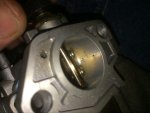
The fuel well is the the cylinder that the the E-tube/Main Jet screw into, correct?

2: Orifices at float level increase low range (early throttle opening) fuel flow by carrying fuel with the airflow to the nozzle.

More Holes at float level to help with more fuel delivery at early throttle opening.
So less holes at top, more holes in middle.... Just trying get an idea of how this info would apply to an optimized E-Tube design. Just some ideas of where I might look to mod an E-Tube for experimenting.

3: Orifices below float level increase fuel flow by the effect of lowering the level of fuel in the well to the hole(s) admitting air. This is like raising the float level a similar amount (increases the effect of gravity in the pressure difference across the main jet) and also adds to the airflow carrying fuel to the nozzle. Locating the orifices at different vertical positions influences this effect’s progression.


Still trying to wrap my head around this one.

4: The "emulsion holes" influence is greatest at low flows and the "main air bleed" has most influence at high flows.

OK now I got to learn the Main Air Bleed on my carb! lol

In the first three cases above, once fuel flow is established it is greater than it would be with fewer or smaller holes. Visualize wind blowing spray off of the top of water waves. It doesn’t take much pressure difference to cause the velocity of the airflow through the bleed orifices to have significant velocity in the orifice, even approaching sonic (1100 F.P.S.) if the orifices are small. The phenomena of critical flow is what limits the total air flow through an orifice and allows tuning by changing bleed size.

Less holes above float level, equal number of holes added at float level to help it off the line and keep total air flow (and hence fuel flow) similar at WOT once fuel flow is established?
Wonder if the 140 E-Tube fit in the 390?

I'll post pics when I get to it.

I'll check if HF has a hole re-locator, but this might require some solder if I decide to experiment.
 

bob58o

SuckSqueezeBangBlow
Messages
9,646
Reaction score
1,846
Location
Chicago-town USA
so where does siri tell you to put a body???:surrender:
Texas!

---------- Post added at 02:57 PM ---------- Previous post was at 02:36 PM ----------

Some more suggestions about using this carb / pump / cam set up

"I use the valve cover to pulse the pump, never had issues. There is a warning with that adapter that states vacuum my not be high enough with some cams to properly pulse the pump. I think this would apply when big CARBS are used as well. If its pumping all right what the heck though. I didn't mention in my earlier reply that we race on oval courses, use torque converters in a "OUTLAW YARD KART LEAGUE" LOL."
 

bob58o

SuckSqueezeBangBlow
Messages
9,646
Reaction score
1,846
Location
Chicago-town USA
Behind those 4 holes is...
Welch or is is Welsh plug?!
Next to idle mix adjustment screw.
 

Attachments

  • image.jpg
    image.jpg
    260.8 KB · Views: 1

bob58o

SuckSqueezeBangBlow
Messages
9,646
Reaction score
1,846
Location
Chicago-town USA
Low circuit air bleed can be drilled an tapped for custom drilled set screw
 

Attachments

  • image.jpg
    image.jpg
    243.8 KB · Views: 3
Status
Not open for further replies.
Top