2020 - GEGcorp "Dirt Bobber Trike"

gegcorp2012

Active member
Messages
491
Reaction score
62
Location
Alabama
Since you don't have 3D CAD,before you do metal works, cardboard linkages simulation is helpful to prevent waste of time and hard labor
cardboard linkages simulation

The film is for rear sus case, front sus is more complicated, scrub should be taken into consideration
Thanks @hodala
I had seen a different video on the Veloped project design, but did not see this one comparing 8 different design options.

Good information for future work on a proper tilting front end... a project for another time.

I will be using physical scale models for the suspension work on my other project, the "Papa Bear" mini buggy build on another thread. See '2020 - Papa Bear buggy' https://www.diygokarts.com/community/threads/2020-papa-bear-buggy.43100/post-545059

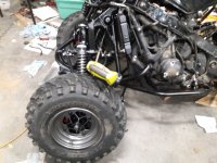
This trike is a side journey, kind of an experiment to test the engine and sharpen my skills for the buggy build.
 
Last edited:

gegcorp2012

Active member
Messages
491
Reaction score
62
Location
Alabama
I was looking for spherical rod ends for my mini buggy build and got an idea to make adapters for the quad front spindles to get to 40 degrees of tilt.

The idea is to use the threaded, conical part of the ball joint and weld that to a small square plate (red) that would have tabs on each side (red) to adapt for the spherical rod ends (blue).

Screenshot_20201117-234009.jpg 20201117_235821.jpg

Here is a drawing for a typical spherical end to show if the size will work.
Screenshot_20201117-235323.jpg
High misalignment bushings will swivel to allow for the steering angle.

This is a photo of bare spindles and steering knuckles for reference.
Screenshot_20201117-232340.jpg
The adapter idea came to me when I started thinking about how to modify the spindles with angle iron and miss the brake piston and hose that passes through the kingpin area.

The adapters will fit in the same space as the stock ball joint (turn 90 degrees to edge) and since this follows the kingpin angle, it minimizes the steering scrub as well.

The only modification to the spindles would be to make a new steering knuckle accept a spherical rod end to work well with the greater tilt angles.
 
Last edited:

Joe-405

Enjoying New Projects
Messages
2,673
Reaction score
69
Location
U.S.A.
That is what I did for the most part on my build off winner spider box build. It worked really well. Gotta have the high misalignment bushings for sure tho.

my thread has pics of the travel. I ended up with a lot. Like 9+” if I remember right.
 

gegcorp2012

Active member
Messages
491
Reaction score
62
Location
Alabama
Hi @Joe-405 ,
The wide part of the Heim joints will be installed vertically, in line with the kingpin angle, so that allows the more extreme angles that come from leaning or tilting.

I see you used an afternarket(?) Banshee front end in 2018. Much better parts thank the odd-ball year, worn out Warrior parts that I am working with in the Covid-19 era.

@hodala ,
I did some modeling work and the 2D model suggests I can have 40 degrees tilt if I make the upper a-arms the same length as the lowers.

20201118_233445.jpg

I ordered a set of 5/8" Heim joints with high misalignment bushings for next week.

I can order some Heim style tie rod ends after I identify the thread pitch.

The plan is to make new upper control arms out of the left over tubing from the quad frame. The frame tubing is a couple of sizes larger than the existing upper A-arms.

I will be moving the upper A-arm pivot points as close as possible in the frame. The steering and the shock pivot have to stay in between the mount points, so this will be fun.

20201118_210159.jpg

Tonight I did some prep work to make a chassis jig to hold the spindles in place and preserve the caster setting while I remove and rebuild the upper a-arms a bit longer and move the pivot points inward.
20201119_235939.jpg

I will be cutting off the anti-sway bar mounting tabs to get a cleaner look.

Next, I cut some wood uprights and drilled them to fit the spindles like a square tire.

20201119_233034.jpg

I had to use the heat and hammer to get the steering tie rod ends out of the knuckles and off the tie rod tube.

Once I ease the upper A-arm ball joint out of the spindle, I will put it back on finger tight and square up the wood brackets and blocks and screw all the wood together to hold the spindles in place while I remove and rebuild the uppers.
 
Last edited:

gegcorp2012

Active member
Messages
491
Reaction score
62
Location
Alabama
I used a square and the laser level to get the lower control arms to 0 degrees for reference. I set it at 0 so it is easier to check as I work on the front end. I set the front wheels so they are strait ahead and secured the wood braces to immobilize the hub/spindles

20201120_211400.jpg 20201121_232549.jpg

Funny to have the spindle and hub just hanging there, but the a-arms can now be removed and re-installed without messing up the caster and KPI. I wrote those measurements on each side for reference.

20201120_230029.jpg

Here is a rough draft of the new upper a-arm. I am planning to re-use the inner mount points and bushings since they will fit inside the frame tubing.

20201121_004040.jpg 20201121_004050.jpg

The ball joint part is just for a trial fit. The new Heim joints will not be here for another week so I have time to clean up the old frame pieces and re-work the inner mount points in the frame.

I spent an hour or more studying the inner part of the frame and steering to determine where I can add strength before I start cutting. All done by crawling around on my knees or looking at pictures after my knees have had enough.

I will have to take off the radiator to get enough room to grind off the monster weld on the anti sway bar mounting tabs. They are on there good.

20201121_003943.jpg

I may be able to reuse the tab plates to tie the steering and shock mounts to the lower frame tubes...
 
Last edited:

gegcorp2012

Active member
Messages
491
Reaction score
62
Location
Alabama
I got a surprise in the mail today, about 3 days earlier that I expected them!

The 5/8" Heim joints with 1/2" misalignment bushings are in.
20201123_123058.jpg

The picture above shows a quick trial fit of one of the joints inside some thick wall rectangular tubing I picked at the scrap yard last week. Its an exact fit, so that's great.

I cut two pieces of tubing to making the Heim [in place of] ball joint adapter brackets discussed in post #122 and highlighted in red. Trying them on the half scale model to make sure I have enough clearance to get the 40 degree tilt.
20201123_210502.jpg
20201123_210625.jpg

The Heim adapters for the top a-arms will be shorter than the bottom ones. That is to gain clearance since the KPI increases the angle on the outer bottom a-arm when leaning into a turn.

Here are a few shots of some frame strengthening brackets that will tie the upper control arm fame to the lower set of tubes. After cutting them out, I used the vice and a sledge hammer to put in a couple of creases to get them to fit better.

20201121_215842.jpg 20201121_230013.jpg 20201121_225908.jpg

This shows the plates in place for a trial fit.
20201124_000523.jpg 20201123_181945.jpg 20201124_211934.jpg
After welding the plates, I can relocate the upper A-arm mounts marked in red in the center picture.
 
Last edited:

gegcorp2012

Active member
Messages
491
Reaction score
62
Location
Alabama
I did some welding today on the Heim adapters. I decided to use the old ball joint studs since they are a direct fit. I had to open up the ball joint to harvest the stud since cutting it flush with the cup would make the stud too short.

20201124_002542.jpg
I used a c-clamp, a washer and a nut that is slighlty larger than the stud to get the adapter and stud lined up for welding.
20201124_002600.jpg
20201124_212154.jpg 20201124_230026.jpg
Here's a side view showing the new bracket and stud in place after removing the washer.
Screenshot_20201124-230159.jpg

Here's some welding on the brackets between the upper and lower control arm mounts along the bottom frame tube.

Screenshot_20201124-232234.jpg
Nice sizzling sound where the bead was tight there for a few CM. Too bad I can't do it like that all the time.
 
Last edited:

gegcorp2012

Active member
Messages
491
Reaction score
62
Location
Alabama
OK, so after 17 days, the 5/8 threaded bungs for the rod ends have arrived !
20201211_130533.jpg
I got a short length of tubing as well, so now I can start on the lower control arms.

20201211_192655.jpg
The shock was being stubborn and did not want to let the bolt slip out, so I did the hack with it along for the ride.
20201211_194759.jpg

Check out the wear on the lower ball joints.
20201212_155758_1.gif

I harvested the old ball joint stud to weld onto the adapter block
20201212_160512.jpg

...then drilled the hole for the 1/2" bolt.

20201211_222207.jpg

Oops. I forgot to go get bolts. Making do with a piece of threaded rod for now. Here is one of the adapter blocks after drilling and trimming. The misalignment bushings are an exact fit for the rectangular tubing.

20201211_203707.jpg

After some test fitting, I was able to tack in the new heim joint and tube. I tied it back to the shock mount and welded to both lower arms.
20201211_221654.jpg

I got one lower control arm done tonight. I will have to do the other side before I start cutting on the upper a-arm supports so I can keep the spindles on both sides locked into the frame and the jig to preserve the suspension geometry.

20201211_230516.jpg

With the adapters and heim joints, I can get more tilt angle than the standard ball joints will allow. The misalignment bushings allow the steering to pivot 21 degrees for low speed turrns.

Screenshot_20201211-235732.jpg
 
Last edited:

gegcorp2012

Active member
Messages
491
Reaction score
62
Location
Alabama
Upper a-arm mounts.
Nice rainy weather gave me extra time in the shop this weekend. The extra time helped to get through the major steps to re-work the upper a-arms.

Here is a shot showing the lower a-arms and the first cut to move the upper mounts inward.20201212_194610.jpg

The most difficult part was to determine where to make the cuts so I can add brackets to move the mount points inside the frame rails.

The original thought was to just cut the brackets out, but the cuts really needed to be in the middle of the a-arm mounts so the longer a-arms can pass through to the inside of the frame.
20201124_000900.jpg 20201213_183831.jpg

I drew up some brackets and cut one to do some test fitting.

20201210_135802.jpg 20201212_220305.jpg 20201213_185621.jpg 20201213_185658.jpg

Then I cut the stock upper a-arms to get the bushing assemblies and to keep the angles used in the stock geometry. I decided to flip the tubes from side to side because the grease fittings were hitting the frame.

20201213_212633.jpg 20201213_212524.jpg

The new a-arm brackets will fit in the gaps that I cut in the frame and allow clearance when tilting.
 
Last edited:

gegcorp2012

Active member
Messages
491
Reaction score
62
Location
Alabama
Upper a-arms
I welded in the new a-arm mounts with the stubs from the original a-arms. then checked to make sire the tubing I harvested from the frame would work to hit the weld up bung for the heim joint.
20201214_191839.jpg
The rear tube needs to have the bend in it.
20201214_201211.jpg 20201214_201528.jpg 20201214_201918.jpg 20201214_202647.jpg 20201214_202654.jpg

Test fit
20201214_203520.jpg
The front tube is too tight to fit over the stub, so I split both pieces a bit to get them together.
20201214_205958.jpg

Tacked the tubes in place until I make the other side.
20201214_214129.jpg

Hit the 10 picture limit : (
 
Last edited:

gegcorp2012

Active member
Messages
491
Reaction score
62
Location
Alabama
A-arms welded up and assembled for a lean test.
20201215_213103.jpg 20201215_213214.jpg

Front view before and after:
20201120_211400.jpg 20201215_213047.jpg

The stock steering rods would be the limiting factor for leaning/tilting today because I noticed the boots had recently been split in a couple of places even though the rubber was in good shape.

20201216_132035.jpg

This stock rod end was bent a little so I got some 10mm Heim joints to replace them.

I ordered some misalignment bushings for the steering rod ends, and they "should" be here by the 23rd.
 
Last edited:

gegcorp2012

Active member
Messages
491
Reaction score
62
Location
Alabama
Final(?) disassembly for paint

I found one part needs a slight adjustment. The first upper a-arm block that I made did not match the scale model when I checked it on the bench.

The part of the Heim joint around the sphere is not perfectly round... it gets thicker towards the threaded end and I missed that detail when laying out that first hole.

As a result, the threaded end is not parallel with the angle of the new upper arm while at the 40 degree (max) tilt.

20201214_112708.jpg
Should be an easy fix with the grinder or a a real pain if I move the holes.

I made the hole a few mm higher for the block on the other side since it was completed last.

20201215_112800.jpg
I used a digital caliper to get the measurement.

Also decided ro tackle one other hole issue. The hole for the "lean lock" needs to move to the left since I had marked one of the edges rather than the center. Ughh... the only thing worse than drilling holes in metal is having to move them
20201216_131150.jpg

On to paint prep...I took the front end off so I could sand everything down to bare metal.

20201216_173105.jpg 20201216_181751.jpg 20201216_221357.jpg 20201216_221407.jpg

I will be using VHT Satin black epoxy with some low key highlights. No more green tape.
 
Last edited:

gegcorp2012

Active member
Messages
491
Reaction score
62
Location
Alabama
Prepping A-arms and shocks... many hours on the flap disk in the angle grinder, the whire wheel in the drill and the coarse Sand Net pads on the sander to get to the original surfaces.

20201218_160449.jpg Screenshot_20201219-120530.jpg

The stock color of the springs is a red epoxy finish, but there's some missing spots and the tops of the springs and they are kind of pitted where the coating peeled over the years and PO painted a couple of times...

Decided to put on a coat of Duplicolor <correction> Graphite colored wheel paint because the shocks were "shiny" underneath the 2 coats of paint and dirt and grease.

The springs can be painted again another color once I see how it looks when it goes back together.

20201219_115304.jpg
I like the way the carbon metallic sprays on and flows out. Its kind of like a hammered finish if sprayed on thick I

Decided to do all the hardware in that color as well. The a-arms will be VHT satin black epoxy for durability.

20201219_122838.jpg 20201219_134541.jpg 20201219_122717.jpg
 
Last edited:

gegcorp2012

Active member
Messages
491
Reaction score
62
Location
Alabama
Wheels tires and spindles getting painted.

Before, during cleaning/masking and after spraying:
20201220_213722.jpg 20201220_213732.jpg 20201220_221219.jpg 20201221_112401.jpg 20201221_112414.jpg

The wheels have seen some really rough terrain during life on the quad. The outer rims are scratched and marred by big rocks and one side was mangled on the inside where it looks like the lugs got sheared or it was ran with the lug nuts loose. Oh well, I sanded, ground and wiper them down and tried to spray that part a little wetter.

Correction on the paint. Its Duplicolor "Graphite" wheel paint.
20201221_103835.jpg
After wire wheel
20201221_104351.jpg
Did an alcohol wipe and masked with tape and a couple of shopping bags
20201221_112017.jpg
20201221_112226.jpg
 
Last edited:

gegcorp2012

Active member
Messages
491
Reaction score
62
Location
Alabama
Got the front a-arms completed and painted all the parts on the front end.

20201222_203732.jpg 20201222_211516.jpg 20201222_220655.jpg

Here's the first lean test with the new Heim joint and longer upper a-arms:20201222_214324.jpg 20201222_214303.jpg 20201222_214211.jpg

Getting 30 degrees of tilt from one side and 25 degrees on the other. I found the lower brackets are hitting the jam nut on the lower Heim joints. I can adjust them out to increase the tilt but then the bracket will hit the threads.
20201222_214624.jpg
Here is the original concept and how the brackets turned out :
20201117_235821.jpg Screenshot_20201222-231916.jpg
 
Last edited:

gegcorp2012

Active member
Messages
491
Reaction score
62
Location
Alabama
The misalignment bushings for the steering tie rods were delivered after Christmas, and ever since, I have been working out the final details on steering with all the new Heim joints.

I had to add some "ears" on the upper and lower heim adapters so they stay in place to ensure clearance for the rims.

20201227_210030.jpg 20201228_224337.jpg

I tried to keep everything as close as possible to the stock geometry, but found that "a bit wider works better" for some of these mods. I went about an inch or so wider on the lower joints to have more clearance for leaning and give the wheels a tad more clearance between the lower a-arms when turning.

Looks like about 32 degrees of tilt may be all I can use... the foot pegs are less than an inch and a half off the ground when tilting or leaning that deep, and there are at least three more restrictions related to the brake line length, shock clearance between a-arms and the articulating arm, etc.

I had to get the saws-all out again tonight to make some room for the inner steering rod ends to the center section of frame where I added the plates (middle of first picture)
20201228_224040.jpg
20201229_231741.jpg

One side is completed, but found yet another clearance issue to work out when I put the other steering rod on. The new brackets are crowding each other.

20201230_000043.jpg
Also found the tie rods are too short now, so I will have to make them longer once I get the brackets and clearances right.

Got to blow it apart again for surgery
 

Attachments

  • 20201229_231741.jpg
    20201229_231741.jpg
    2.8 MB · Views: 2

gegcorp2012

Active member
Messages
491
Reaction score
62
Location
Alabama
OK, here are some photos of the paint and final suspension upgrades for the 2020 season.

I was able to get everything back together in between the rain and drizzle for a quick yard test including an unintentional donut, and one I did for the photos below.
trike_test_donut_12-31-2020_1.gif


20201231_153851.jpg 20201231_153909.jpg 20201231_153931.jpg 20201231_154006.jpg
Also took it up the road (2nd gear) for a one handed steering stability test and made couple more photos on red dirt then stopped by to show it to one of my Harley riding, DIY type neighbors.

Screenshot_20201231-162152.jpg 20201231_155039.jpg 20201231_155127.jpg 20201231_155205.jpg 20201231_155048.jpg

The trike ran great and handles better than it did before with the limited testing I could do today.

Happy New Year !
 
Last edited:

gegcorp2012

Active member
Messages
491
Reaction score
62
Location
Alabama
Final update for 2020 Build Off:
Tonight I went through and counted up the cost to complete the Dirt Bobber leaning trike as you see it above.

$400 Wrecked CBR 1000F
$200 Yamaha 350 Warrior frame
$200 welding supplies and power
$260 Repairs to bike - radiator, fan, throttle grip, front end bearings, bushings, brake M/C, calipers
set, starter solenoid, warning lights
$310 Modifications from stock - Heim joints, high misalignment bushings, longer cables, stick coil ignition upgrade
$50 Paint and detailing like new lug nuts

<about $1500 rolling>

$340 New tools - Floor jack, band saw, SyncPro carb sync tool, Honda tool kit

I estimate that I spent around 275 hours working on the Dirt Bobber... that is based on 137 posts at around 2 hours in the shop to do anything worth writing about.
(that's 6.8 work weeks of 40 hours).

I thoroughly enjoyed the project to keep me occupied during COVID lockdown and to learn more about building with tubes and the front suspension parts.

There are a couple more mods that I may do later:
1) The Kenda Big Block knobby tire for traction
2) Sprocket set to "slow it down".

What is the performance potential using a $400 bike motor ???

Here are a couple of screen shots showing the projected shift speeds using Gear Commander and the lowest gear sprocket set I have found so far (14/44)

Screenshot_20201214-142239.jpg Screenshot_20201126-051409.jpg

Yah, the biggest problem is the loose nut behind the wheel.
 
Top