2020 - GEGcorp "Dirt Bobber Trike"

gegcorp2012

Active member
Messages
491
Reaction score
62
Location
Alabama
Check this out... It should allow me to keep the trike vertical and ride on a <edit> 15 degree slope also.

20201026_083538.jpg
 
Last edited:

gegcorp2012

Active member
Messages
491
Reaction score
62
Location
Alabama
Thanks @landuse.

Template time for the lean lock (or electric kickstand)

Thanks to @Functional Artist for the question that led to an action (where's that old power window regulator motor) that turned into an idea (hey, that might fit) that proved to be a workable concept (if the whole motor could slide); and now it's roughed in.

Heres a recap of what I had in mind...

It is a motor driven screw that will lock the articulating shock mount in the "neutral" or non-tilting position.

Less words, and more pictures, right !
20201026_160238.jpg 20201026_160252.jpg 20201026_160320.jpg 20201026_193812.jpg
It was a challenge to get the holes in the right places, especially the motor mounting holes WRT the motor shaft. I decided to use construction nails as motor slide rails that will allow the motor to move as the threaded rod turns.

20201026_202937.jpg20201026_205211.jpg

Here's how it lines up...
20201026_205247.jpg
The nails will be welded to the plate and the threaded rod will be welded onto the window motor drive gear and the nut will be welded to the plate and the plate will be welded to the frame horns.
20201026_205817.jpg
The motor is at a slight angle because clearances are tight between the frame horns.
20201026_210028.jpg 20201026_210907.jpg

Now I have to get some welding gas and some parts at the hardware store to complete the assembly... a grade8 non-galvanized bolt, some nuts and washers.

That is the total cost for the electric kickstand. DIY in a few hours is priceless !
 
Last edited:

gegcorp2012

Active member
Messages
491
Reaction score
62
Location
Alabama
Adjusted total cost upwards about 6 bucks for nylock nut upgrades and a non-galvanized bolt.

Here is the final assembly and welding

20201027_225624.jpg

Welding the bolt to the motor sprocket was a pain to align and it's not perfect, but there's enough wiggle room that it works without binding.

20201027_225945.jpg 20201027_230022.jpg

Tacked to frame.
20201027_230928.jpg 20201027_231015.jpg
Still need to drill a hole for the lean lock "pin" in the front shock mount.
20201027_231317.jpg

Also need to find an automotive window or seat switch that will reverse the polarity and mount somewhere convenient.
 
Last edited:

gegcorp2012

Active member
Messages
491
Reaction score
62
Location
Alabama
I finished the welding on the front end. Used the laser level to try and get a reference line (blue masking tape) to work from.
Screenshot_20201030-011634.jpg
Cut pieces then welded them in and re-assembled for a test drive.
20201028_234337.jpg 20201029_133131.jpg 20201029_144601.jpg 20201029_135458.jpg
 
Last edited:

gegcorp2012

Active member
Messages
491
Reaction score
62
Location
Alabama
Made a low speed riding video today.


Video was taken the day after tropical storm Zeta blew through, and the yard is very wet, so low speed balance and coordination testing in the driveway today.

Video was shot with a full HD Android phone and a cheapie 720 dash camera.
Both cameras were stationary because I had my hands full.

Edited with Shotcut with two video and two audio tracks. I used keyframes to pan and zoom the stationary shot like someone was working the camera. Audio is the natural audio from each camera, each in a channel to give a nice stereo effect.

Wear ear buds to enjoy the exhaust tone and the burnout!
 

gegcorp2012

Active member
Messages
491
Reaction score
62
Location
Alabama
Looks good.

Have a look at all the threads posted by Hodala
...
Hi @landuse , Thanks again for the reference to @hodala and his threads. I checked out several threads on his work a few months ago.

I really liked a section from one of the videos showing the way the suspension works when traversing the side of a roadway.

Also the CAD modeling examples makes me wish I had taken some CAD courses back in the day. I find it true that if you can draw it or model it accurately, there is less need for rework once you build it.

I have a nice ditch in my yard that I can try to go across diagonally, (very dangerous tipping hazard before I tried the anti-sway bar). I will be sure to try to catch it on video in a way that captures the moment.

The greatest differences are the weight, the power levels and the speed that our 3 wheeled craft are designed for.

Since I am building with a heavy 1000 cc engine and frame, the weight, high center of gravity and relatively narrow front track width (41" |o-o| )are a few of the biggest challenges for my build.

Leaning is DEFINITELY the way to go to take out some of the scare factor on a "tippy" reverse trike. I would like to get to 30 degrees of tilt, but getting to the next level will require a set of custom a-arms.

I found an electric reverse leaning trike build on YT that was inspiring since the build was using an ATV frame and front end. It is called the Cyber Trike.

Recently the guys at Grind Hard Plumbing put out a video of a snowmobile to reverse trike conversion they did, and that is a closer match to what I am hoping to do with this experimental build.

Emphasis on mental.

Then I found that Yamaha bought a patent for a leaning trike and seeing that design in a powerslide I became determined to make mine a leaner and scrap the anti sway bar.
 
Last edited:

gegcorp2012

Active member
Messages
491
Reaction score
62
Location
Alabama
"Lean Lock" electronics.

I found a power window wiring diagram online and noticed that I need relays to keep from having to switch so much current.

I found these relays and sockets in my automotive project pile on the back burner and snagged them.

20201028_180819.jpg

Touching the [lock+] or [unlock+] line to 12v will pick one relay and turn the motor in that direction.

I found these little momentary switches in our electronic picker tub and made a switch panel from a thin piece of wood and put the panel on the upper frame rail.
20201105_232204.jpg
Then I soldered up the relays and motor connector and put the relays in the electrical area under the instrument cluster. The arrow shows where I get the 12v for power from the low beam relay connector since it is hot with the key on.

20201105_230154.jpg
I will pick another circuit with a lower amp fuse since the lights are 20A...

Here is the Lean Lock in operation :

20201105_232336.jpg 20201105_232414.jpg
 
Last edited:

gegcorp2012

Active member
Messages
491
Reaction score
62
Location
Alabama
Lean Locker and suspension demo video.


I spent the week trying to shoot a multi camera video in less than an hour before dark since the time change.
Monday's shoot was spent trying to get cameras to stick to somewhere on the trike.
Tuesdays shoot was an attempt to use a helmet cam and a phone like before... but bad composure and too dark to use.
Wednesdays shoot was a bit better video, but boring low speed stuff, I just worked with the video files in Shotcut
Thursdays shoot one camera was not recording, so I had to re-do.
Fridays shoot
made the cut, so I show the suspension and the Lean Locker demo with some yard ripping.
 

gegcorp2012

Active member
Messages
491
Reaction score
62
Location
Alabama
Experimental noodling...
Last week I got the trike up to 55-60 mph and noticed some front end shimmy where I may need a simple toe in adjustment, or it might be extra slop somewhere like the tie rod ends.

I have not done any alignment or adjustments (besides the obvious hacking the bike/quad into a leaning trike) ... and now I am really considering how to replace those lower ball joints.

Can't seem to stop thinking about those lower ball joints being so loose... There is an animated GIF on page 2 or 3 of the build showing this issue, and I am still using those sloppy ball joints.

Now that it is a leaning trike, I want it to lean more... I would like to get 30-45* of lean out of the front end, but think it would take a re-design for that purpose rather than asking the stock a-arms and knuckles do more of the unintended leaning it is doing now.

I know... proceed with caution.

So the trickiest part of the Yamaha 350 Warrior a-arms is the angle that the ball joint cup is held WRT the a-arm.

Both a-arms have the cups at an angle. The lower a-arms are about 4* and the upper a-arms are about 7*. I tried measuring physically and decided to try and take some pictures that could be scanned into CAD software or be used to make measurements or a model with.

Trying to see if my new ball joints with 30* movement will increase the lean or not if I keep the stock cup angles.

20201103_002628.jpg
Anyone want to be a CAD mentor ?
I was thinking a photo could be used to take measurements off of and to make a model

20201110_232255.jpg
I set up some reference marks on the garage floor so I can take more photos as needed and have consistency.

Leaning right and left...
20201110_230421.jpg 20201110_230326.jpg

Leaning and turning hard right and left so you can see the ball joint cup angles. There is blue tape around the steering knuckles where the ball joint attaches.
20201110_230113.jpg 20201110_225926.jpg
 

Functional Artist

Well-known member
Messages
4,403
Reaction score
1,678
Location
Toledo, Ohio
Nice work! 🤠
Looks like it functions pretty well :thumbsup:
...so, why would/do you want it to lean more?

Also, them front tires have a lot of "side" grip :unsure:
...has that been an issue?
...&/or could that cause problems, with more leaning?
 

gegcorp2012

Active member
Messages
491
Reaction score
62
Location
Alabama
Hi @Functional Artist

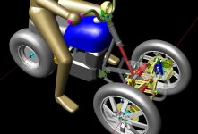
More lean would give better handling in turns where the terrain is not flat.

Typical roadways have less than 5 degrees of tilt, but in the yard or off road, I am trying to make turns or go straight on a 600 pound "street bike" where there are slopes greater than 15 degrees.

As speed increases, I have noticed the trike wants to steer by leaning rather than turning (just like a bike), as long as I do not exceed that 15 degree limitation while carving a turn. When I hit the 15*, that limits the arc I can carve in a turn, and the throttle or brake has to be used to prevent unwanted interference with trees, rocks, cars, concrete blocks or whatever may be there in the yard to drive around.

Experience... the hard teacher:
I figured this out the hard way by running over an 8" concrete block with the left front wheel the other day.

I was coming up from the "bottom" of the yard, (uphill slope) and trying to carve a minimum radius turn while pouring into second and then third gear, saw the block would be in my path and was leaning all I could but was not able to get the trike to turn any more to match the line I was committing to with the throttle. I applied the rear brakes (too little, too late) and ate that concrete block with a very slight bump - not enough to throw me or pull the handlebars loose from my hands (since my front shocks are now twice as long), but hitting anything as big and solid as a concrete block should be avoided.

Now I have to watch my LF tire for lumps bumps or bruises from that 20-25 mph impact.

Here are some things I have been thinking of as a fix:
1) Disassemble and move on <not yet>
2) Ride slower <nah>
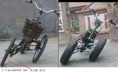
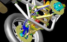
3) Lean more (fix ball joints in the process)
4) More grip on rear tire to bring the rear around in a powerslide
5) Extend foot pegs to get leverage for more weight transfer when standing on the pegs.

Thanks for your comments and ideas.
 

hodala

Member
Messages
177
Reaction score
5
Location
Taiwan
If you want to build a Tilting trike, you have to abandon your ATV frame and suspension parts and build a whole new system

The picture was drawn for a 450cc bike, not completed
 

Attachments

  • 20 11 11.JPG
    20 11 11.JPG
    59.5 KB · Views: 3
  • TT450a.JPG
    TT450a.JPG
    84.5 KB · Views: 3

hodala

Member
Messages
177
Reaction score
5
Location
Taiwan
More pictures
 

Attachments

  • f sus 2.JPG
    f sus 2.JPG
    83.3 KB · Views: 3
  • 輪轂.JPG
    輪轂.JPG
    47 KB · Views: 3
  • 16吋前輪圈b.JPG
    16吋前輪圈b.JPG
    84.6 KB · Views: 3
  • 20161002.JPG
    20161002.JPG
    132.1 KB · Views: 3

gegcorp2012

Active member
Messages
491
Reaction score
62
Location
Alabama
Thanks @hodala

Using a modified ATV frame and stock suspension, I have demonstrated it is possible to build a tilting trike with 15 degrees of tilt using ATV parts.

I like your 450cc project and thank you for showing detail of how you reach a 40 degree tilt angle.

A 40 degree tilt angle is much safer than only 15 degrees because it allows the rider to decide how far to lean. This is good for safety.

I see that the ATV steering knuckles and ball joints will bind at higher tilt angles, and the better designs use Heim joints instead of ball joints.

This is easy to see comparing your CAD views to stock ATV parts tilting at 15 degrees.
20201103_200033.jpg

Thanks again for sharing your experience.
 

hodala

Member
Messages
177
Reaction score
5
Location
Taiwan
Also know about this; a+2b will reduce the tilting angle quite a lot

My 1st generation bicycle derived from the motor scooter,the same geometry, b of the bicycle larger than the scooter
 

Attachments

  • a+2b.JPG
    a+2b.JPG
    134.9 KB · Views: 4
  • lean angle bike vs bicycle 2.JPG
    lean angle bike vs bicycle 2.JPG
    112.7 KB · Views: 4
Last edited:

gegcorp2012

Active member
Messages
491
Reaction score
62
Location
Alabama
Thanks @hodala
I made a model last night to learn more about the limitations using the ATV parts.

I found the normal vertical travel is great since the ATV suspension was designed for off road, and there is some KPI to minimize the scrub radius and compensate for unequal length control arms.

Using the model (and studying photos) helped me see that the outside upper ball joint is binding at 15 degrees of tilt. The ball joint has about 30 degrees max angle, and this is used up without making 30 degrees of tilt on the trike.

20201113_141914.jpg 20201113_141750.jpg 20201110_230729.jpg
Next parts needing rework would be the steering rod ends.

If the trike could be tilted more, the short upper a-arm could fall through or hyperextend between 25-30 degrees of tilt.

20201113_095532.jpg

At 30 degrees of tilt, the upper control arm is holding the tire off the ground, not normal.
This shows some of the reasons why a tilting trike requires a different design than typical ATV parts.
Thanks again for helping me understand this.
 
Last edited:

hodala

Member
Messages
177
Reaction score
5
Location
Taiwan
Since you don't have 3D CAD,before you do metal works, cardboard linkages simulation is helpful to prevent waste of time and hard labor
cardboard linkages simulation

The film is for rear sus case, front sus is more complicated, scrub should be taken into consideration
 
Last edited:
Top