I like that seat 
You are using an out of date browser. It may not display this or other websites correctly.
You should upgrade or use an alternative browser.
You should upgrade or use an alternative browser.
2020 - GEGcorp "Dirt Bobber Trike"
- Thread starter gegcorp2012
- Start date
Brianator
Gettin' er done!
Me too that's cool! Is that alligator skin? Please take video of the tire roasting! Lol
gegcorp2012
Active member
Hey, so the seat is advertised as alligator skin, so it's an alligator pattern for sure, but don't smell like leather (Not sure what reptilian hide would smell like). My guess is its some kind of pleather. (plastic leather)
Anyways you get the point. Should be a wild ride, like sitting on the shout of an alligator, right ?
I worked on the seat pan some today, and concluded I will have to make it custom to fit the frame since it was intended for a Harley or other bike.

I used two pieces of angle iron and a couple of sharp blows with the sledge to make a quick bending brake, and put a crease line to fit my new tank support.

The seat pan is supposed to flip upward from the rear and use the same mount bolt as the rear of the tank. I will have to add some mounting tabs if I keep this pan.
The material is too thin IMHO and I don't think it will hold my weight bouncing around on it unless it is well supported undereath.

The seat really needs to be moved back a couple of inches from the tank rather than sitting right on it.

....so if I move the seat back where it needs to be, I have to add on to the frame rails where I cut out the bent stuff.

Thinking I need to do something like this:
Sent from my SM-J700T using Tapatalk

Anyways you get the point. Should be a wild ride, like sitting on the shout of an alligator, right ?
I worked on the seat pan some today, and concluded I will have to make it custom to fit the frame since it was intended for a Harley or other bike.
I used two pieces of angle iron and a couple of sharp blows with the sledge to make a quick bending brake, and put a crease line to fit my new tank support.
The seat pan is supposed to flip upward from the rear and use the same mount bolt as the rear of the tank. I will have to add some mounting tabs if I keep this pan.
The material is too thin IMHO and I don't think it will hold my weight bouncing around on it unless it is well supported undereath.
The seat really needs to be moved back a couple of inches from the tank rather than sitting right on it.
....so if I move the seat back where it needs to be, I have to add on to the frame rails where I cut out the bent stuff.
Thinking I need to do something like this:
Sent from my SM-J700T using Tapatalk
gegcorp2012
Active member
Tilting tank and sissy bar are ON.

For the sissy bar, I bent up a couple of tubes and added some smaller tube and made plugs for extra strength.


This is the left inside one that will not show. Always try to do your best work in the areas nobody will ever see.
Then I drilled the hole for the rear tank support. This will hold the tank and allow it to tilt up.
 Left side

Right side
After the welds cooled off, I tested the tilt...


It works great ! Better than stock.
About this time, I started thinking
"Wow this is going better than I expected, I must be on a roll! "
...so I decided to take the tank outside and put some gas in it to see if the new o-rings are sealing.
Here's how that went:

Bad leak on fuel sender
So the o-ring for the fuel sender was leaking. It was the correct diameter, but not thick enough, so I am trying a large flat rubber washer.

While I had the sensor out, I added the ground wire and extended the signal wire, then tried measuring the sensor resistance and it was open.
...so I took it apart and re-soldered the sensor wire and cleaned up and a bunch of muddy varnish from the windings.


Tilting seat
I could not use most of the brackets that came with the seat pan, but one of them will work. I will use it at the tank support and make a thicker and longer seat bracket from flat bar.


Sent from my SM-J700T using Tapatalk
For the sissy bar, I bent up a couple of tubes and added some smaller tube and made plugs for extra strength.
This is the left inside one that will not show. Always try to do your best work in the areas nobody will ever see.
Then I drilled the hole for the rear tank support. This will hold the tank and allow it to tilt up.
Right side
After the welds cooled off, I tested the tilt...
It works great ! Better than stock.
About this time, I started thinking
"Wow this is going better than I expected, I must be on a roll! "
...so I decided to take the tank outside and put some gas in it to see if the new o-rings are sealing.
Here's how that went:
Bad leak on fuel sender
So the o-ring for the fuel sender was leaking. It was the correct diameter, but not thick enough, so I am trying a large flat rubber washer.
While I had the sensor out, I added the ground wire and extended the signal wire, then tried measuring the sensor resistance and it was open.
...so I took it apart and re-soldered the sensor wire and cleaned up and a bunch of muddy varnish from the windings.
Tilting seat
I could not use most of the brackets that came with the seat pan, but one of them will work. I will use it at the tank support and make a thicker and longer seat bracket from flat bar.
Sent from my SM-J700T using Tapatalk
Last edited:
gegcorp2012
Active member
Tilting seat
Need to make a stronger seat mount using some 3/16 flat bar.


I used my flame tip carbide burr as a center punch and it works better than any of the dull punches that I cannot find today.*

Been using a step bit to see how long it will last. I put a drop of oil on each hole and some on the bit between holes.

I used a jig saw with metal cutting blade to connect the holes.

Added a couple of square pieces with holes in the center to accept the mounting bolt.

Then did a trial fit to see how to round off the corners. Looks like I will have to move the mount back a little so the tank will have the room it needs to tilt.

Sent from my SM-J700T using Tapatalk
Need to make a stronger seat mount using some 3/16 flat bar.
I used my flame tip carbide burr as a center punch and it works better than any of the dull punches that I cannot find today.*
Been using a step bit to see how long it will last. I put a drop of oil on each hole and some on the bit between holes.
I used a jig saw with metal cutting blade to connect the holes.
Added a couple of square pieces with holes in the center to accept the mounting bolt.
Then did a trial fit to see how to round off the corners. Looks like I will have to move the mount back a little so the tank will have the room it needs to tilt.
Sent from my SM-J700T using Tapatalk
Nice work
gegcorp2012
Active member
Thanks !
Hopefully this week will be the first rolling test.
There are still a couple of rocks in the gas tank, final routing of wires and hoses (where does this one go?) and I have to make a battery box removable... and probably several other things that will need to be taken care of.
By the end of the week, there should be some interesting "brake tests", some "one wheel peel" launches, and hopefully some fun laps on the yard track for the first test day.
Here is the preliminary seat arrangement. I raised up the front of the seat because it fits better, but I'm still not sure if the springs are going to help, they seem pretty stiff for my old bones.


 [73c8d3bf197cfd4d9fd574a.jpg[/IMG]


The main thing at this point is staying on it and in control to have a good ride while feeling out the balance and handling.
Sent from my SM-J700T using Tapatalk

Hopefully this week will be the first rolling test.
There are still a couple of rocks in the gas tank, final routing of wires and hoses (where does this one go?) and I have to make a battery box removable... and probably several other things that will need to be taken care of.
By the end of the week, there should be some interesting "brake tests", some "one wheel peel" launches, and hopefully some fun laps on the yard track for the first test day.
Here is the preliminary seat arrangement. I raised up the front of the seat because it fits better, but I'm still not sure if the springs are going to help, they seem pretty stiff for my old bones.
The main thing at this point is staying on it and in control to have a good ride while feeling out the balance and handling.
Sent from my SM-J700T using Tapatalk
gegcorp2012
Active member
Running and rolling.
Made a couple of burnouts and set the idle, then took it for a lap around the yard track.
I let it cool for a bit, then started it easily for the second video.
I took it around the track in first gear and no more than 15 mph on straitaway, with a throttle "goose" here and there, but had to go much slower on the curves.
When riding, it wants to lean away from the turn (bad understeer) so I didn't push it at all.
The engine/radiator was hot enough for water to leak from a loose hose clamp, but the fans did not kick on, also the mechanical driveline speedo works, but the tach and temp guages were not working.
So it is idling better, but still needs to have the carbs balanced and I need to check out the cooling fan situation.
The Dirt Bobber Trike has electric start, it runs and drives: The clutch and shifter linkage is working, it has kill switches that work, and the front and rear brakes work. It moves under its own power....


Turning the handlebars it feels like a quad, If sitting still and you lean one way or the other, it kinda feels like a bike but the front wheels lean in the direction of the bike.
Once it's rolling, it's another story... the similarities between quad and bike go away. it does not feel like a bike or a quad in a turn.. now it's a research project to figure out how to get the front suspension to "lean the other way" if possible. (sway bar?)
Now I have two DIY builds in the yard !

Sent from my SM-J700T using Tapatalk
Made a couple of burnouts and set the idle, then took it for a lap around the yard track.
I took it around the track in first gear and no more than 15 mph on straitaway, with a throttle "goose" here and there, but had to go much slower on the curves.
When riding, it wants to lean away from the turn (bad understeer) so I didn't push it at all.
The engine/radiator was hot enough for water to leak from a loose hose clamp, but the fans did not kick on, also the mechanical driveline speedo works, but the tach and temp guages were not working.
So it is idling better, but still needs to have the carbs balanced and I need to check out the cooling fan situation.
The Dirt Bobber Trike has electric start, it runs and drives: The clutch and shifter linkage is working, it has kill switches that work, and the front and rear brakes work. It moves under its own power....
Turning the handlebars it feels like a quad, If sitting still and you lean one way or the other, it kinda feels like a bike but the front wheels lean in the direction of the bike.
Once it's rolling, it's another story... the similarities between quad and bike go away. it does not feel like a bike or a quad in a turn.. now it's a research project to figure out how to get the front suspension to "lean the other way" if possible. (sway bar?)
Now I have two DIY builds in the yard !
Sent from my SM-J700T using Tapatalk
Last edited:
gegcorp2012
Active member
I found a few interesting articles on Motorcycle.com comparing a Can Am Spyder to a Slingshot and a Morgan reverse trike, and the Spyder seems to be the closest match to what I am attempting.
A little searching of front suspension diagrams confirmed there is a anti-roll (sway) bar on the front control arms.
I made some measurements and came up with a plan to add some mounting tabs outside the down tubes between the steering and frame. That area is open enough to sneak in a bar if it is the right shape.


I started down a path to piece together a DIY bar, and after a few clicks in eBay, I found a complete stock Spyder sway bar for less than $60 bucks, so I ordered it.

Just have to wait and see if it fits , but this should take care of the suspension roll issue.
Sent from my SM-J700T using Tapatalk
A little searching of front suspension diagrams confirmed there is a anti-roll (sway) bar on the front control arms.
I made some measurements and came up with a plan to add some mounting tabs outside the down tubes between the steering and frame. That area is open enough to sneak in a bar if it is the right shape.
I started down a path to piece together a DIY bar, and after a few clicks in eBay, I found a complete stock Spyder sway bar for less than $60 bucks, so I ordered it.
Just have to wait and see if it fits , but this should take care of the suspension roll issue.
Sent from my SM-J700T using Tapatalk
gegcorp2012
Active member
Got the anti-roll bar, and am working through the "best fit" scenarios. I think I like having the bar mount to the down tubes and the ends of the bar facing the front.
The angle iron is temporary - to hold the bar close to the preferred mounting height for the photo op.


The next night, I made a CAD template (cardboard assisted design) for mounts to weld on the down tubes to carry the roll bar.
I will have to relocate the brake hose retaining clips and add some tabs to the upper control arms to attach the bar.
"just a couple hours work", right ?!
Sent from my SM-J700T using Tapatalk
The angle iron is temporary - to hold the bar close to the preferred mounting height for the photo op.
The next night, I made a CAD template (cardboard assisted design) for mounts to weld on the down tubes to carry the roll bar.
I will have to relocate the brake hose retaining clips and add some tabs to the upper control arms to attach the bar.
"just a couple hours work", right ?!
Sent from my SM-J700T using Tapatalk
gegcorp2012
Active member
Getting around to it...


Sent from my SM-J700T using Tapatalk
Sent from my SM-J700T using Tapatalk
gegcorp2012
Active member
Stabilizer bar continued.... with the mounting brackets cut, bent and drilled, I was able to bolt on the stabilizer bar and start the final positioning.
I am planning for wheelies (full droop), followed by a rapid compression towards near full bump as the weight of the trike and rider come back down.
I used an angle finder on the right control arm as viewed from the front (driver's left) and raised all the weight off the suspension and took a reading, then stood on the very front of the frame and took a reading, then measured again at unloaded ride height. Those angles were drawn on paper.
Then I lined the bar up on the bench and set up a 90* reference mark, lined up the stabilizer bar links to the preferred neutral position, and made some maximum tilt measurements for the misalignment bushings.
The results are good, showing I should be able to make some controll arm mounts that will hold the link end and not snap it as the control arm angle changes ~ 45 degrees from full droop to full bump.
I am having some trouble accessing the site with Tapatalk, and the web browser does not allow my stock resolution photos to be uploaded, so no pics until I get that issue resolved.
gegcorp2012
Active member
Images using Brave web browser on Android still too large. <error>...
I am having some trouble accessing the site with Tapatalk, and the web browser does not allow my stock resolution photos to be uploaded, so no pics until I get that issue resolved.
Lower resolution JPG screen shots are smaller in size and work

Karts of Kaos
the many mowers guy
is this road legal if so you should go through the drive through. lol
gegcorp2012
Active member
Suspension measurements:

Stabilizer bar link bushing max angles:


Stabilizer bar link bushing max angles:
Attachments
-
 20200826_131256.jpg3.3 MB · Views: 1
gegcorp2012
Active member
is this road legal if so you should go through the drive through. lol
Seriously doubt getting on the road to cruise the drive through or buzz the local Sonic.
Here's how it looks getting into 2nd gear in the yard....


Last edited:
gegcorp2012
Active member
Got the anti-sway bar mounts and the control arm link brackets built. I took extra time to get everything centered at ride height and tacked it all into place.
Then I raised the front end and checked the sway bar links with the suspension at full droop and the links are clearing the brackets, so I can do the final welds then take it for a test run.


Then I raised the front end and checked the sway bar links with the suspension at full droop and the links are clearing the brackets, so I can do the final welds then take it for a test run.
Last edited:
gegcorp2012
Active member
Here is a comparison of the suspension roll before the anti-sway bar:


Here is the full lean test with the anti-sway bar installed :


With rider leaning to lift a tire:


Bouncing with my weight loading the springs.

Here is the full lean test with the anti-sway bar installed :
With rider leaning to lift a tire:
Bouncing with my weight loading the springs.
Last edited:
gegcorp2012
Active member
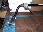
One more control mod... last night I decided to hack up the foot brake and make it more conventional.
The standard rear brake lever is too far back for the new foot placement. Being aware of this, I tested the use of the "heel actuated" brake a few times and found that it took me an extra 1-2 seconds to apply the brake because I am so used to pressing down with the front of my foot rather than my heel.
Seconds matter when you really want to stop, so I'm taking care of it now.
Less than 5 seconds with the grinder....

Needs to miss the new foot rest and the oil filler on the engine case

Trying some flat bar, but did not have a sharpie handy

The standard rear brake lever is too far back for the new foot placement. Being aware of this, I tested the use of the "heel actuated" brake a few times and found that it took me an extra 1-2 seconds to apply the brake because I am so used to pressing down with the front of my foot rather than my heel.
Seconds matter when you really want to stop, so I'm taking care of it now.
Less than 5 seconds with the grinder....
Needs to miss the new foot rest and the oil filler on the engine case
Trying some flat bar, but did not have a sharpie handy
Last edited:
gegcorp2012
Active member

After making the first weld, I discovered the rear brake needed to be bled out. I pressed the lever and it bottomed out against the foot peg.

The fluid was pretty nasty, so I opened the bleeder valve on the rear caliper and pumped the reservoir dry then cleaned it out with a rag. Then a fresh fill of DOT4 brake fluid and some more pumping 'til it started running clear again.
Now it has 1/4 or more space before bottoming out. I'm hoping the rear brake grabs hard enough to lock up the tire now. It was feeling pretty weak before I chopped and lengthened the lever, so we'll see if the extra leverage and fresh fluid helps.
Next, I did some poking around on wiring and found my new key switch is slightly different than the busted stock one. The new one sends power to one 12v circuit, while the original switched two 12v circuits, so I chose Ignition <of course!>.
I hot wired the fan temporarily, and worked through the cooling fan circuit because the last time I rode it (2 miles on the trip meter now) the fan did not seem to want to kick on, even as the temp guage started responding (just normal temp, not showing in the red on the gauge). The radiator near each of the sensors was measuring around 190*F with an IR thermometer.
I didn't want to push the temp any higher before making sure the replacement fan actually works. (It does)... just needs a ground shot in place of the temp switch on the bottom of the radiator to kick on.
Verified my original fan is in working order as well. I took the original thermo switch from that one and put it in a pot of boiling water to make sure it would click into conducting mode, but could not get it to do so.
Gotta do some more research on that part and see what temp it is supposed to kick on at.
Next, I started working on a misfire on the right set of pipes (the right side without a muffler) .
Turns out the number 3 plug boot is not seating well at all.


The boot on the left has a flatter shape and debris under it, and the brass contact for the plug is discolored, so it appears that it was running with the plug wire loose for some time before I got the bike.
A little research on the CBR Forum and I find out I have to order a motorcycle tool kit because the plug wrench is a 18mm thin wall, and I verified I don't have anything that will work.
ETA on tools to do a plug change will be sometime next week.
Also found out the plug wires have a resistor element that turns out like a carb jet, and is spring loaded, so I took the one out of number 3 to get a better look.

So I scuffed it up as good as I could with a wire brush and screwed it back in about half way. That adjustment made it so the connector grabs the plug head much better and pulls the boot down.
In the process, I pulled the boots off each one of the plugs and ran my magnetized screwdriver around the valve cover and plug hole to clean up several "beards" of metal particles that must have been flying around the shop as I used the cutoff wheel and welder nearby.

Don't want any of that junk to fall in when I pull the plugs.
So.... Here is what it sounds like from a cold start, not using the choke. It takes several tries to catch and run, so a real tune up is in order, but it revs up to 6k and that's my threshold for pain and itchy eardrums in the shop.
Bummer...
The site does not allow audio file types to be uploaded.
I got rid of the pervasive misfire coming from #3 and wanted to celebrate the occasion sharing an audio recording.
Will have to make a video, I guess....
Last edited: