
Hello,
I am posting a thread I placed in another location in this forum in hopes of getting some help here since I haven't received much from my original post. I have literally been so close to getting this kart running for a few days but I am really at a loss right now. Please take a look through the post below and ANY help at all I would appreciate it greatly!
I am posting a thread I placed in another location in this forum in hopes of getting some help here since I haven't received much from my original post. I have literally been so close to getting this kart running for a few days but I am really at a loss right now. Please take a look through the post below and ANY help at all I would appreciate it greatly!
My Original PostI have a 150cc Carbide reverse that is not starting.
I have checked for spark by pulling the plug and grounding it. No spark.
Brand new battery - no luck
New ignition coil / spark plug - no luck
Put in new CDI - it literally melted - old one is back in
New carb - (air fuel and idol set are not set correctly for sure, they are bottomed out and turned back 2 full turns, figure I cant do anything until I can start it)
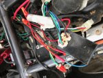
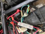
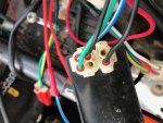
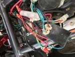
Looking at the CDI and comparing it to the diagram found buggydepot.com I do not have a Kill Switch wire going into the #5 pin of the CDI. I am also completely missing the #4 ground wire that is suppose to be there.
-I read somewhere about jumping the killswitch to rule out while diagnosing the spark issue and it specifically mentions the above wires(it doesnt say to totally remove them so I have NO idea what is going on)
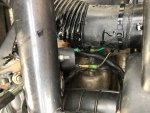
-I was starting to troubleshoot the stator and it asked me to disconnect the Black/Red and yellow/blue wires coming from the stator to the main harness but noticed only the yellow/blue wire is connected to the harness and the black/red is just one have of the bullet type connector with no mate to plug into. Its like the male connector with no female connector.......(pictured)
At this point I figured it best to seek some professional help because I am now lost completely...........
- The only reply Ive received thus far"Looks like you're missing a wire. The black/red should run to pin 6 on the cdi. Trace the wire from pin 6 and see if you find anything. If not, hook it up somehow. The ground should be coming out of the same conduit stuff as the other cdi wires (From what I remember . If it's not there, just hop pin 4to bare metal to try to get a spark and figure it out later. I'd just hop it to the negative battery terminal to make sure you have a good connection."
The last comment I have made on that thread.I can not find any other wire that the red/black would go to. So just hook the black red into the CDI at #6 and ground it to the battery?
So i am out here working on this thing now and think there is an issue with either what you were saying or this POS. You were sayin the black red goes to the CDI at pin 6 but if you look at the pics I posted originally there is a black wire already installed at pin 6 and pin 5 is empty. That still leaves the red and black just dangling around. Put it in pin 5??
Attachments
-
 IMG_1784.JPG139.4 KB · Views: 10
 -
 IMG_1781.JPG125.4 KB · Views: 9
 -
 IMG_1782.JPG108.7 KB · Views: 10
 -
 IMG_1786.JPG102.9 KB · Views: 7
 -
 IMG_1785.JPG138.5 KB · Views: 10
Last edited: