Tsunami (2024) Electrathon Racer (#47) "T for Victory"

Master Hack

Well-known member
Messages
4,263
Reaction score
6,828
Location
Mountain top Labratory
How ya notchin? Drill press and hole saw?
nice work.
Egor and l had an intervention with my inner junkman.
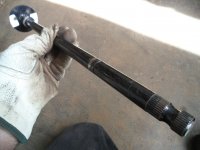
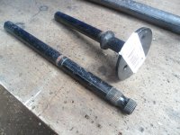
Seems he is actually looking for a shaft drive thingy.
 

Functional Artist

Well-known member
Messages
5,604
Reaction score
3,213
Location
Toledo, Ohio
How ya notchin? Drill press and hole saw?
nice work.
Egor and l had an intervention with my inner junkman.
Seems he is actually looking for a shaft drive thingy.
Hey T,

Naw, I do 'em DIY ;)

I just use a cut off wheel
...& a router :thumbsup:

"intervention"?
Things gettin' outta hand out there? :huh:

If you want this thing?
...or any parts?
...just let me know :cheers2:
 

Functional Artist

Well-known member
Messages
5,604
Reaction score
3,213
Location
Toledo, Ohio
The third level would be the roll bars/cage

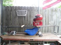
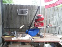
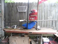
Started on mock up with some props
SAM_2916 (1).JPG
Gonna have (2) roll bars
...maybe in a triangle style

(High...Ducky) :)
SAM_2918 (1).JPG
...or maybe in more of a box style
SAM_2920 (1).JPG
FYI: The closest Electrathon America racing near me (~100 miles away) uses/goes by a modified EA rule book.

Most of the main/basic concept(s) are the same
...but, they have added some "extra" rules :confused:

ChallengeUSA
https://drive.google.com/file/d/1lyOtDExh5oUlSKFWA7ZaVGW64BS-AwiH/view

Like this:
ROLL CAGE
1. Vehicles must be equipped with a roll cage and driver compartment that will withstand
impact and protect the driver. The Driver Compartment is defined as the portion of the
car that the driver is completely contained within. The roll cage must extend high enough
to provide clearance above the helmet of the tallest driver.
2. The driver’s helmet must be positioned directly below the roll cage and centered front to
rear and side to side.
3. The roll cage will consist of two continuous loops that begin and finish at the base of the
chassis and may be either longitudinal or transverse in configuration, with cross bracing
between the loops to connect the two, centered over/above the driver’s helmet.

a. The roll bar must be braced to the chassis, forward and rearward. The rearward
brace will be no more than six inches vertically from the top of the roll bar. The
forward bracing shall form a protective cage around the driver and be designed to
protect the driver from front and side impact
b. Frontal driver protection is determined by drawing a straight line horizontally
across the roll cage frame members in front of the driver’s face. The straight line
should be a minimum of two inches from the driver’s face when wearing a helmet

4. The roll cage must be made of tubing that meets the minimum standards for frame
components (see item #1 in Chassis/Frame/Crash Protection above).
5. An inspection hole, at least .125” in diameter must be drilled into a non-critical area of
the roll bar to permit inspector confirmation of wall thickness
6. All parts of the driver must be completely inside the frame cage at all times when in the
normal driving position, with hands on the steering mechanism in any position


Here are some of the basics :sifone:

ChallengeUSA Electrathon Rules
Effective January 1, 2023

Foreword

Welcome to the 2022-23 ChallengeUSA Electrathon season! As the ChallengeUSA
Electrathon Coordinator, it is my pleasure to introduce you to the latest rulebook.
To help you with the development of your vehicle there are design rules and guidelines
that must be followed. The design process needs to result in two products that will be evaluated
during the challenge. The first product is a vehicle report (monthly log books and a final report)
that outlines the processes that the design teams underwent to design and build an Electrathon
vehicle. The second product is the car itself, which will be inspected for safety and compliance
with the rules of the challenge. The rules, procedures, and evaluation scheme are outlined in this
document. Lastly, each design team participating in a ChallengeUSA event will test their
vehicles on a defined route in one of the ChallengeUSA competitive events. The testing process
will establish the ability of a vehicle to brake, maneuver, and test the endurance of the vehicle.
By giving teams multiple testing opportunities, members can learn from their problems and
engineer better solutions for continued testing from challenge to challenge.

There are some notable changes that have been made this year to help create the best
experience possible for all ChallengeUSA Electrathon teams. We have expanded to four
different competition classes, which allows entry-level teams to compete against other entry
level teams, and separates AGM and gel-cell battery vehicles from lithium battery vehicles. We
have also aligned many general vehicle design rules to align with the ChallengeUSA
Supermileage vehicles, to allow a retired gas-powered car to be converted to an electric car and
vise-versa.

The ONLY change from the previous set of rules to this year focuses on batteries:
Effective immediately (for the 2023 spring race season), all electrathon vehicle endurance
competition batteries, regardless of chemical composition, are limited to a total of 1200 watt
hours in the system, as calculated based on manufacturer battery specifications for voltage and
amp hours. Vehicles that contain a total of more than 1200 watt hours must have a cycle analyst
or similar technology that can track watt hours utilized during an endurance heat, so that event
officials can observe the cycle analyst to verify watt hours used.
Current vehicles (including teams that have already purchased materials for the 2023 race
season) would be grandfathered into this rule and allowed to have over 1200 watt hours in the
endurance competition battery system. By the start of the 2026 race season, all vehicles would
need to be under the 1200 watt hour limit.
Any vehicles over the 1200 watt hour limit in 2026 and beyond will be considered an exhibition
vehicle, will not be eligible for awards, and will still have to use a cycle analyst to remain under
1200 watt hours used in an endurance heat to maintain a safe event.
 

Functional Artist

Well-known member
Messages
5,604
Reaction score
3,213
Location
Toledo, Ohio
Here is some more info (for those who may not wanna "look it up themselves" :cheers2:

Competition Classes

CLASS OVERVIEW
The purpose of the Challenge USA Electrathon classes is to allow cars/drivers to compete
with their peers. Cars are assigned to classes based on their cost and different design criteria. To
encourage new construction and designs, no vehicle may compete in Classes 1, 2, 3, or 4 for
more than three years. After the third year that a vehicle competes, its chassis must be retired,
although other components of the vehicle may be used in future vehicles. During the second and
third year that a car competes, two of the major systems (frame, electronics, steering, brakes,
body, suspension, motor/drivetrain, and wheels) must be modified from the previous year’s
competition. These changes will be documented in monthly and final reports.
The intention of the vehicle class system is to foster creativity among teams and
encourage students to continually look at how to make improvements to their vehicles. As such,
the system is designed for vehicles to only be allowed to “move up” a class. If a vehicle in an
“Entry” class finishes in the top half of the class in total season points, that vehicle is required to
move up to the corresponding “Advanced” class the following year. Cars in an “Advanced” class
that finish in the bottom half of season points for the class may not move down a class, but will
remain in their current class.

CLASS 3 – ENTRY LITHIUM
Overview
• This vehicle must be a first-year car, or the car must not have placed in the top half of the
season ranking for all Class 3 vehicles from the previous year’s competitions
Design Components
• Vehicles must follow the “Vehicle Design Rules” as outlined in the next section AND...
o Chassis must have an enclosed body except for driver entry and egress. All vehicle
components and the driver’s body must be enclosed within the body.
Cost
• The vehicle must cost less than $3500. Teams may have extra parts, such as additional
sets of batteries, tools used in the pits, spare vehicle parts, and driver safety equipment.
The cost of the vehicle is determined by the cost of all materials and components on the
car at the time it is presented for competition.

Braking
• No regenerative braking systems allowed (aside from those pre-built into hub motors)
• Vehicles must have braking mechanisms on at least three wheels
Batteries
• Batteries may be any type of sealed production batteries that are under 1200 watt hours
• No solar panel recharging permitted during the challenge, however using solar panels to
recharge batteries before the endurance competition is permitted

Vehicle Design Rules

The following vehicle design rules are generic to all ChallengeUSA Electrathon vehicles. If the
rulebook does not explicitly state that something is allowed, it is not allowed without approval
from ChallengeUSA officials.

GENERAL
1. There is a $3500 limit on the value of the material used in the construction of Class 1 and
Class 3 cars, excluding brakes or professional welding for critical safety items
a. This $3500 limitation is for the parts and materials used in the construction of the
car as it is presented for the competition
b. This $3500 limitation specifically excludes driver clothing and safety equipment,
pit tools, spare parts, and spare batteries
c. This $3500 limitation does include the batteries in the car during the competition
d. Student labor is not charged and factored into this limit, but other “volunteer
labor” must be included in the vehicle cost at a reasonable rate
e. All teams are required to submit documentation (needs a link) with any car
entering a competition. This documentation must include a listing of ALL
material used in the vehicle, regardless of whether it was purchased or donated.
Documentation is to include the actual/estimated value and the source of the
material. Documentation must also include an estimated value of volunteer labor.
These forms must accompany the vehicle in order to enter a competition, even if a
team does not complete the final report.

2. The maximum length of a ChallengeUSA Electrathon vehicle is 12 feet. The maximum
width is 4 feet (measured at the widest point of the entire vehicle with body material
attached.
3. The minimum track width (measured from the center of one wheel to the center of the
opposite wheel) is 24”.
4. The maximum weight of a ChallengeUSA Electrathon vehicle is 350 pounds.
5. Cars with a wheelbase of less than 6’ must have a lower center of gravity to prevent
rollovers
6. No vehicles may be designed in a way that would position the driver’s head in front of
his or her torso, or legs. The driver must be positioned feet-first in the vehicle.

CHASSIS/FRAME/CRASH PROTECTION
1. All vehicles must have frame members that protect that driver in the event of a collision
from any direction The minimum size of all frame members that protect the driver (any
frame member from the seat forward) and protect the batteries will be 1” OD round or 1”
square tubing with the following wall thicknesses:
• .0625” (16 gauge) for mild steel

2. Behind the firewall (except around batteries) .750” OD round or .750” square tubing will
be allowed
3. Frames for Class 4 vehicles may be constructed of other materials, provided that it is
demonstrated and documented that alternative materials provide equal or greater
structural strength and protection
4. The vehicle must have a fixed floor pan the prevents any part of the driver from
contacting the ground
5. Minimum ground clearance for any vehicle will be 2”. •
Vehicles with tires that have a sidewall height of over 2” must have a ground clearance
that exceeds the height of the tire sidewall to keep the vehicle off the ground in the event
of a flat tire
6. Maximum ground clearance will be no more than 8”
7. Each vehicle shall have structural members that meet frame member requirements at the
front of the vehicle that act as a bumper to protect the feet of the driver and to prevent
intrusion into another vehicle in the event of a crash. The minimum dimensions of these
structural members shall be eight inches vertically and eight inches horizontally (that will
not fit through the 6” space defined in item 8 below). Any material in front of this 8”
bumper must be collapsible so as to not intrude into another vehicle in the event of a
crash, Teams must be able to demonstrate that the material is collapsible with minimal
force during the inspection process (can be done using a video taken at school, does not
need to be destructive)
8. Frame members on the side of vehicles must be designed to help prevent another vehicle
from intruding into the driver’s compartment in the event of a crash. No spacing larger
than 6 inches is allowed on the frame of the vehicle around the front and sides of the
driver’s compartment and the battery box(es), as tested with a 6” diameter disc. The 6”
disc must be prevented from intruding into the driver compartment by 1” OD (square or
round) tubing
9. Side impact protection must extend up to the top of the driver’s shoulder

ROLL CAGE
1. Vehicles must be equipped with a roll cage and driver compartment that will withstand
impact and protect the driver. The Driver Compartment is defined as the portion of the
car that the driver is completely contained within. The roll cage must extend high enough
to provide clearance above the helmet of the tallest driver.
2. The driver’s helmet must be positioned directly below the roll cage and centered front to
rear and side to side.
3. The roll cage will consist of two continuous loops that begin and finish at the base of the
chassis and may be either longitudinal or transverse in configuration, with cross bracing
between the loops to connect the two, centered over/above the driver’s helmet.
a. The roll bar must be braced to the chassis, forward and rearward. The rearward
brace will be no more than six inches vertically from the top of the roll bar. The
forward bracing shall form a protective cage around the driver and be designed to
protect the driver from front and side impact
b. Frontal driver protection is determined by drawing a straight line horizontally
across the roll cage frame members in front of the driver’s face. The straight line
should be a minimum of two inches from the driver’s face when wearing a helmet
4. The roll cage must be made of tubing that meets the minimum standards for frame
components (see item #1 in Chassis/Frame/Crash Protection above).
5. An inspection hole, at least .125” in diameter must be drilled into a non-critical area of
the roll bar to permit inspector confirmation of wall thickness
6. All parts of the driver must be completely inside the frame cage at all times when in the
normal driving position, with hands on the steering mechanism in any position

INTERIOR
1. Padding is recommended, but not required be installed on all frame/roll cage members
from the driver’s waist up.
a. Padding (if it exists) is suggested to be at least .5” thick and made of closed-cell
foam (most pipe insulation has a .5” wall thickness)
b. Padding (if it exists) is suggested to be installed using a method other than cable
ties

2. A head restraint, capable of withstanding a force of at least 100 pounds in the rearward
direction, is required to prevent whiplash.
a. The head restraint is recommended, but not required to be padded with at least .5”
thick closed-cell foam

3. All Class 3 and Class 4 vehicles must be equipped with a full firewall behind the driver,
extending from the floorpan of the vehicle to the rollbar, and from one side of the seat to
the other. The only openings in the firewall should be for the safety harness, and should
be as small as possible
a. The firewall will help protect the driver in the event of a chain breakage, and will
prevent clothing from being caught in the drivetrain
 
Last edited:

Functional Artist

Well-known member
Messages
5,604
Reaction score
3,213
Location
Toledo, Ohio
Rules, shmules.
Hey EZ,

Well...if your racer doesn't meet/qualify with "their" (specific) rule book
...they won't let ya race :mad2:

Hmmm...this (6") spacing requirement seems confusing
...are they referring to something like the "slats" in a baby bed? :huh:

8. Frame members on the side of vehicles must be designed to help prevent another vehicle
from intruding into the driver’s compartment in the event of a crash. No spacing larger
than 6 inches is allowed on the frame of the vehicle around the front and sides of the
driver’s compartment and the battery box(es), as tested with a 6” diameter disc.
The 6”
disc must be prevented from intruding into the driver compartment by 1” OD (square or
round) tubing
 

Master Hack

Well-known member
Messages
4,263
Reaction score
6,828
Location
Mountain top Labratory
Functional Artist

Well-known member
Messages
5,604
Reaction score
3,213
Location
Toledo, Ohio
The previously mentioned DP vice and a hole saw. Try it, ya might find it easier, and less painful.


"things" are always outta control when my inner junkman and Egor start conspiring.
Hey T,

I have a tube notcher (~10 yrs old)
...but, I "spun" the bearing in it, while trying to use it to "notch" pipe
...& found that it's "way harder" to use a hole saw on 1/8" walled pipe (remember I usually build with 1/2" Schedule 40 water pipe)

So, now, I just cut each piece (to length)
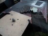
...which seems to reduce wasted material (them 1" "slugs")

Then, I cut (2) opposing "V's" ~1/4" deep (with the cut off wheel)
...& then, round the "V's" out with a ~1" round grinding stone, mounted in an old router
SAM_2898 (1).JPG
I can "knock" a bunch of 'em out quicker than, I can hole saw 'em
...& it seems ta produce pretty good results :thumbsup:
SAM_2923 (1).JPG
Also, got another tip :cheers2:

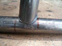
Once ya know where ya want a piece, to intersect with another piece, ya mark it (like in the pic above) ;)
...but, when, ya clean it up for weldin', ya "clean" your mark(s) off too :mad2:

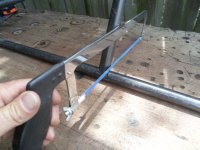
So, before "cleaning" I just use a hack saw, to make a non-cleanable mark
SAM_2924 (1).JPG
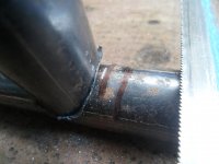
Like this
SAM_2926 (1).JPG
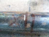
Then, when you remove the piece & clean 'er up you can still see/find your marks :2guns:
SAM_2929 (1).JPG
Sorry, forgot to get an "after clean up" pic :huh:
...so, you'll just have ta use your imagination) :banana:
 

Functional Artist

Well-known member
Messages
5,604
Reaction score
3,213
Location
Toledo, Ohio
Well, you have it figgered out, with good results. I never have been able to do much of anything with a cutoff wheel, other than cut off.
Never mind me....

Hey T,
The more ya work with stuff...the more proficient ya get at it :cheers2:

I need some steering bearings & mounts
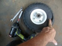
...so, I'm gonna harvest the hubs off a couple of old HF hand dolly wheels (1 white & 1 silver)
SAM_2935 (1).JPG
Yup, "this little guy" :thumbsup:
SAM_2936 (1).JPG
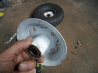
Another project for the cut-off wheel :sifone:
SAM_2938 (1).JPG
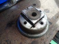
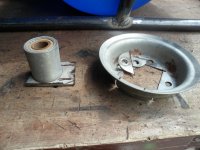
...& it sliced & diced it, pretty easily
SAM_2940 (1).JPG
I found this double ended steering shaft at BMI Karts (~$10.00)
SAM_2943 (1).JPG
...so, I cut 'er in half (I'm gonna use 1/2 of it, for this project & the other 1/2 for another)
SAM_2945 (1).JPG
I'm thinkin' something kInda like this ;)
SAM_2959 (1).JPG
 

Functional Artist

Well-known member
Messages
5,604
Reaction score
3,213
Location
Toledo, Ohio
Repurposing at its finest!
Hey T,

Ya can't beat (4) free bearings
...& a couple of bearing holders outta the scrap pile :)

but

I didn't like the upper, over the top mount :huh:
SAM_2960 (1).JPG
So, I made another (dash bar & mounting bracket)
SAM_2966 (1).JPG
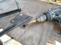
For the new upper mounting bracket, first I used a Step Drill Bit ta drill out a couple of switch (On/Off & Reverse) holders
SAM_2974 (1).JPG
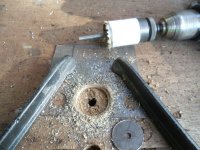
Then, a hole saw ta cut out an area for the bearing & holder :thumbsup:
SAM_2975 (1).JPG
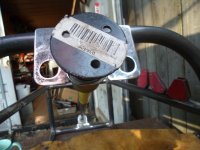
Turned out kinda like this :sifone:
SAM_2977 (1).JPG
Yea! I like that more better :bannana:
SAM_2976 (1).JPG
 

Functional Artist

Well-known member
Messages
5,604
Reaction score
3,213
Location
Toledo, Ohio
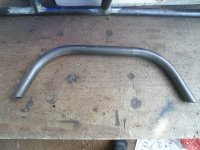
Hey, how are you bending that tube?

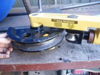
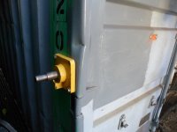
Well, I bought a China-cheap tube bender a few years ago (~$120.00)
SAM_2950 (1).JPG
...& some 1" tube (14g & 16g)
...but, my first experience wasn't that great :ack2:

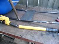
I broke the handle on the bender :furious2:
SAM_2953 (1).JPG
...& also, ended up terminating the project (GT-E) due to a FATAL design flaw :mad2:

GT-E build thread
https://www.diygokarts.com/community/threads/gt-e.44560/

The first time I mounted the bender to the back/bed of my truck
...& tried using a horizontal "pulling action"
...but, it wasn't easy (very little physical leverage)
SAM_6685.JPG
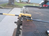
This time I mounted it to the side of my steel shipping container
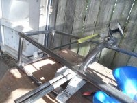
SAM_2954 (1).JPG
This way, with a vertical/downward "pulling action" I have much more leverage
...so, I'm doing more practicing
...& am starting to get better results :sifone:
 

Master Hack

Well-known member
Messages
4,263
Reaction score
6,828
Location
Mountain top Labratory
It takes some serious muscle to bend 1 x .120 tubing as you know,
are you manually calculating your bends?
what is your bend radius.
you obviously have it figgered out.
l’m too stoopid to do manual calcs, so l rely on software.
 

Functional Artist

Well-known member
Messages
5,604
Reaction score
3,213
Location
Toledo, Ohio
Hmmm...this (6") spacing requirement seems confusing
...are they referring to something like the "slats" in a baby bed? :huh:

8. Frame members on the side of vehicles must be designed to help prevent another vehicle
from intruding into the driver’s compartment in the event of a crash. No spacing larger
than 6 inches is allowed on the frame of the vehicle around the front and sides of the
driver’s compartment and the battery box(es), as tested with a 6” diameter disc.
The 6”
disc must be prevented from intruding into the driver compartment by 1” OD (square or
round) tubing

Jeez, it sounds like they want you to have a funny car cage around the head area.
Hey Denny,

I found a Electrathon America Challenge USA video, that explains this 6" spacing rule a bit more ;)
...& it covers some other rule info too :thumbsup:
 

Denny

Canned Monster
Messages
11,889
Reaction score
8,357
Location
Mayberry, Indiana
That roll cage is a joke that they show on that kart. If these guys are engineers who made the rules and specs we’re in trouble as a country. I think you could beat these genyusis easily. And do it safer too!
 

Functional Artist

Well-known member
Messages
5,604
Reaction score
3,213
Location
Toledo, Ohio
That roll cage is a joke that they show on that kart. If these guys are engineers who made the rules and specs we’re in trouble as a country. I think you could beat these genyusis easily. And do it safer too!
Hey Denny,

Ya, for teaching kids/young adults about engineering
...ya don't see them using much triangulation
...or very many triangles in/on a lot of them racers :unsure:

So, for "the class" let's expand on this topic a bit :thumbsup:
...what don't ya like about that roll cage?
...& why?
 

Denny

Canned Monster
Messages
11,889
Reaction score
8,357
Location
Mayberry, Indiana
It’s too narrow. In a simple rollover your head (helmet) would come into contact with the pavement. That would be a big no, no! Roll bar padding should go around the bars completely and not be made of pool noodles. I have the same complaints about most of the buggies sold today. The reason they make the cages narrow at the top is to keep them from sitting upside down. Which is great, but and it is a big one. They do not allow side protection around the head and shoulders. Which could come into contact with the ground.
 
Top