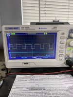
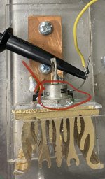
Anyone try PWM controller?

Master Hack

Well-known member
Messages
1,983
Reaction score
3,173
Location
Mountain top Labratory
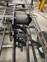
This is my “other” project. I scored an electric lawnmower motor and matching 36v battery.
I’m using them on my rechargeable “lawn kart’.
Think John Deere Gator. This is “Naughtagator”
So i made it work with an ebay controller that lasted about 12 minutes. Now l’m building my own. Does anyone here have any experience with pulse width modulation circuits?
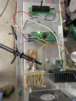
I built this thing using a 555 chip and a pair of big mosfets. It works on the bench, but before i put it to work and release the smoke, l’m asking for tips.
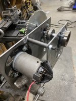
3B191A04-2E24-4046-AECE-7FE25A3CF80C.jpegFF277075-E46E-4763-ABB1-75802969CD4C.jpeg
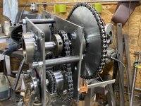
24:1 gear reduction
DD1AF270-0B0C-4766-A6B4-D718594F3ABA.jpeg
 

Functional Artist

Well-known member
Messages
4,411
Reaction score
1,694
Location
Toledo, Ohio
What are your motor specs?

This is totally different than what your workin' with
...but, here is my second endeavor with building an electric powered kart
 

Master Hack

Well-known member
Messages
1,983
Reaction score
3,173
Location
Mountain top Labratory
What are your motor specs?
That is my biggest problem with this. There is absoultely nothing to identify this motor.
l don’t know HP, RPM, wattage, i don’t even know the brand. I do know it’s 36 volts, thats it. It works and it was free. I have driven the contraption around, and my guess work was pretty accurate. My PWM controller works, it provides great variable speed control, just not very long. The components are up to the task but there are some transient currents or something cauing problems. I’m closing in on a solution and might have it on verion 3. Just wondered if any one knows anything about PWM circuits, What does everyone use for motor control?
 

Master Hack

Well-known member
Messages
1,983
Reaction score
3,173
Location
Mountain top Labratory
What Ebay controller did you already try?
This joke: https://www.ebay.com/itm/234324540095
the first one was DOA the second lasted 12 minutes and got so hot the components were falling off the board.
if you have an off the shelf that works please share.
l’ll give mine one more try, with some improvements. Gas engine is on standby.
the only reason l’m liking electric is reverse is so easy.
 

Functional Artist

Well-known member
Messages
4,411
Reaction score
1,694
Location
Toledo, Ohio
That's more like for a power tool (think like a router speed controller)

Maybe, look up the specs, for the type of lawnmower, that the motor came off of.
...but, you may find that it's just not usable on a kart.

Spinning a blade to cut residential grass (~1') is a way different "load" than, trying to motivate a 200 -500 lb. kart

Check out my Hell-raiser kart (AKA "Predator Eater") :devil2:
 

Master Hack

Well-known member
Messages
1,983
Reaction score
3,173
Location
Mountain top Labratory
I was skeptical about the motor at first, but it works well for this project. I have 24:1 gear reduction. top speed is only about 7 mph. This is grandpa’s kart for hauling tools and things around the property. Its more of a motorized wheelbarrow than a go kart.
The only problem is the controller. My MO is to make everything possible myself. I don’t buy anything unless l absolutly can not make it here.
beautiful kart BTW.

Motor and gearbox:FA2A722F-EEA7-4C3A-93A0-D4F052756CE2.jpegAACF86F3-7029-44E8-AC72-D641694BFF8D.jpeg
 

Functional Artist

Well-known member
Messages
4,411
Reaction score
1,694
Location
Toledo, Ohio
Thanks! :cheers2:

I try-n-make most stuff myself too :thumbsup:
...but, I've found that sometimes, ya gotta "pick your battles" ;)

Well, then maybe something like this, might work.
It seems to be about the biggest size that they make/use for 36V motors on go karts

36V 800W Brushed motor Speed Controller (~$30.00)
https://www.ebay.com/itm/264470839625?hash=item3d93b0c149:g:EVUAAOSwGe5dg0xU&amdata=enc:AQAHAAAA8AlG3EkIf2qbhj69cqD4UhydU50iQVoS8XrSD6VC/ER8UX5E8BtSOwhwHEhx03RzaSlFcrZJSSTiwukaKh/cCOhOH9v+xcHKOKaxOXHZ7LqeTEcs+ips5CefPWHNE2bboLf4CjoRs4gfvZ/4KWTCmfwEZFXvjs1RixklvtIv93Upmlc8HVj4jF4Nrtk+bQrSCtxcVXyHeThtuY9Whk6d3TlgqegjPeoMXPZNBCF75l6N18s0UeUQQ+0VRd1JcyTyQRX7YNA8KS3UJBvyll42OaN2chwT/ZF+ngVzlnH4AZcc0VzZfEblxZq0cWHU2uhQGw==|tkp:Bk9SR8DIqJjxYA

* The 36V golf carts use bigger SC's
...but, they are much more expensive & require more "hardware" (big fuses, contactor etc.)
 

Functional Artist

Well-known member
Messages
4,411
Reaction score
1,694
Location
Toledo, Ohio
I'm too stupid for that! I'll struggle with something until I've been defeated about 15 times before I give up!
Um...they say that admitting it is Step #1 :lolgoku:
but,
As (we) get older (we) should try-n-work "smarter" ;)
...not "harder" :cheers2:
&
I've found that "doing this" leaves a lot more time to tackle, the tasks that we "can" accomplish :2guns:
 

65ShelbyClone

Active member
Messages
623
Reaction score
97
Location
SoCal
The components are up to the task but there are some transient currents or something cauing problems.

What part of the circuit is failing and how? I don't see any flyback diodes for protecting your FETs. You might also do well to use some gate drivers depending on what their specs are.
 

Master Hack

Well-known member
Messages
1,983
Reaction score
3,173
Location
Mountain top Labratory
What part of the circuit is failing and how? I don't see any flyback diodes for protecting your FETs. You might also do well to use some gate drivers depending on what their specs are.
This sounds like the kind of help l’m looking for!
what l was using doesn’t matter much anymore, l let the smoke out of em! I’m starting fresh agin. I had the circuit working perfectly under no load condition. As soon as l put it under load the mosfets would start conducting 36v in 36v out. There was no way to turn ‘em off. l even diconnected the battery, waited a couple of minutes, then connected battery. the motor started running instantly, with no way to stop it.
l’m back to the begining, so i’m open to any and all suggestions, schematic, ideas and or parts. l did install a diode on the gate along with a 1 meg resistor to ground. No help.
smoke was released when l started poking around. To make it more interesting, l have no specs on the motor. I had 2 mofets in parallel that were 50 amp 50 volt IIRR.
There is a 100 mp fuse between the battery and controller and it has not blown.
 

65ShelbyClone

Active member
Messages
623
Reaction score
97
Location
SoCal
There's a lot going and bear in mind that I'm only self-taught in electronics.

Your FETs stuck on because that's usually what happens when they fail. The gate doesn't need to have a diode on it(see 2nd paragraph); it only needs a discharge resistor to ground so it will shut off quickly. That's the thing with FETs; they have to be switched very quickly so they're either fully on or fully off. The more time they spend in the transition, the more heat they dissipate. The gate resistor value vs. switching time can be calculated using the datasheet's gate capacitance. 1 megaohm is way too high for this application. It's likely going to be in the hundreds of ohms, not millions, but also keep in mind that the resistor goes directly to ground and current through it when the gate is on should not exceed the resistor's rating. There should also be a resistor between the gate and whatever is supplying the gate signal(the 555?). The gate capacitance will pull a lot of initial current when it starts charging and that could exceed the signal source's rating, eventually damaging it.

Flyback diodes are reverse biased on the load. When the FET shuts off an inductive load like a solenoid or motor winding, the field collapse creates a high reverse voltage spike (the flyback voltage) on the FET's drain/source pins that exceeds the FET's breakdown voltage and will damage it. A flyback diode acts as a backward short for that voltage and prevents it from damaging the FET. Shottky barrier diodes are preferred for this role because they have very fast switching characteristics.

Your FETS are also way too small for the job. When you look at the datasheet's "Absolute Maximum Ratings" section and it shows 50A of current or something, there's almost no practical way to keep it cool at that current and the current capacity goes down rapidly with temperature(shown in a chart in the datasheet). You would need probably 10 or more of those FETs in parallel with good cooling to handle a 100A load reliably.

That brings me to the final point: your motor probably draws more than 100A at low speed and high load. It would be helpful to know what the original mower's advertised specs were(wattage, horsepower, whatever). Barring that, you can try to measure the winding resistance and deduce how much current they're capable of pulling at 36V.
 

Master Hack

Well-known member
Messages
1,983
Reaction score
3,173
Location
Mountain top Labratory
Well thats some info l can work with, thank you.
I’ll do some recalculating, as apparently what l’ve done is way off. In the mean time is this a suitable flyback diode? I did have it installed on the load side.

C8A00A73-8136-4F73-8B10-2954F00A4471.jpeg
 

65ShelbyClone

Active member
Messages
623
Reaction score
97
Location
SoCal
All I can tell about the diode is that it's from International Rectifier and was made in Mexico. Need a part number/datasheet.

As for the IRLBA1304P, not really. Your battery voltage is really close to the absolute maximum voltage rating. The datasheet also says that it can handle 175A continuous, but look closer at the footnotes where it says the package limitation is 95A. The plastic encapsulation adds thermal resistance and makes it impossible to run the junction (silicon that makes up the transistor) at 175A. The 95A package limitation is also at the max junction temp of 175°C. It won't last long being run that hard.

I don't want to discourage anyone from learning this stuff and DIYing, but there is a reason 300A+ PWM dc motor controllers cost hundreds of dollars. I went down the road you're headed and came to the same conclusion that others before me had; it's impractical to build something like this based on analog electronics and without either an EE degree or a lot of time to learn how to design it.
 

Master Hack

Well-known member
Messages
1,983
Reaction score
3,173
Location
Mountain top Labratory
I love talking to geeks! You figured this stuff out in the school of hard Knocks or what? You either had some schooling or a mentor or inhaled a lot of burnt silicon smoke!:oops: I have a PHD from the school of hard knocks! But that just gives me a skewed vision of some things. Thank You for your input here. While this looked simple on the surface once I burnt up my stash of mosfets, it became obvious there is more to it. I'm no engineer, just show me a print and I'll make the part. This mysterious world of invisible electrons is too complicated. Its fun screwing with the stuff making sparks, burning silicon and on rare occasion making something that actually works. I don't want to put a bunch of dollars into this thing, it just isn't that important. Thank you for your input again and I'll get the standby gas motor ready! Admit it you are a geek:banana:
65 shelby clone? That gets my ears at attention! 15CTSV here.
The term geek is only intended as a compliment!
 
Last edited:

Functional Artist

Well-known member
Messages
4,411
Reaction score
1,694
Location
Toledo, Ohio
Um...didn't someone mention "sometimes ya gotta pick your battles"? ;)

Well, I guess you got to your "defeated 15 times" mark :rolleyes:

Don't give up on electric
...it's the way of the future :cheers2:

Maybe check out !ARRIBA! :sifone:
...the fun starts @ ~2:25 min (1, 2 & 3) :smiley_omg:
All I can say is "pure power" :bannana:


Master Hack

Well-known member
Messages
1,983
Reaction score
3,173
Location
Mountain top Labratory
I have reached my limit of 15 failures and l am admitting defeat! I am retreating back to the part of the shop with carburetors gas cans and exhaust fumes. Its where a dinosaur like me feels comfortable. "pick yer battles" "can't teach an old dog new tricks" "admit defeat" bla bla bla.
I'm licking my wounds and conceding this is a case of the wrong stuff on the wrong chassis. Free isn't always a good deal!
The standby gas engine is getting prepped, now I encounter another problem. I robbed the TC off the red kart to put on the new motor and now I find the 5HP honda has a 3.75 inch long shaft and the clone motor has a 2.25 inch long shaft. I figured out I have gotten the shaft and need to do some research into shafts, TC's, yada yada. Obviously the TC is not going to fit on this motor.
While I am defeated, I still had fun playing with this stuff and learned a little at the same time. I won't give up on electric, I'll just delay it until the electric stuff gets easier and cheaper. I believe it took Edison several attempts to make a working light bulb. Yeah, no comparison!
 
Top