Full Suspension Big Block Mini-Buggy Build

SquidBonez

Active member
Messages
512
Reaction score
132
Location
New Jersey, USA
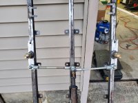
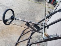
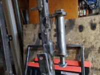
Been working on this build little by little. Got the front bumper/foot guard on and modified my pitman arm even more. Also modified the steering links.
20211104_162257.jpg
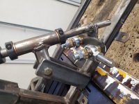
I added another piece of 1/4" flat bar with two holes to the pitman arm so I could have shorter bolts (less stress versus one long bolt). It also allows me to use misalignment spacers.
20211104_163304.jpg
20211104_163255.jpg
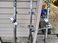
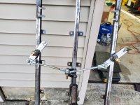
As for the links I added an outer tab for the tie rods going to the spindles.
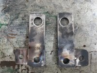
20211104_170024.jpgI just hope that I get enough steering angle out of this setup. I tested it out by just holding a piece of tube and connecting the heim joints to the spindle/pitman arm and I'm only getting about an inch and a half of movement. Granted this was a 40" piece of tube while the tie rods going to the links will be about 7". Do shorter tie rods create more movement? I might have to end up redesigning the steering. At least I have a spare steering shaft...
 
Last edited:
SquidBonez

Active member
Messages
512
Reaction score
132
Location
New Jersey, USA
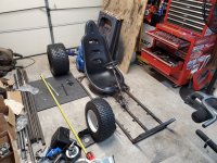
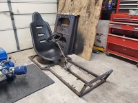
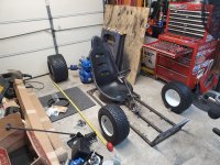
Decided to do another mock-up with the engine in place to figure out how long this thing would be. With my current plan it would have roughly a 70" wheelbase - WAY too long. I want the wheelbase to be as short as possible.
20211105_185259.jpg
I wanted to ditch the engine-on-swingarm design and have the engine mounted to the frame. I was going to run a jackshaft that both powers the rear wheels and acts as a pivot for the suspension. It was just going to be a solid axle. Now I'm not so sure. I also toyed with an IRS design but then I was going to have to run multiple chains, create custom chain tensioners, and need to run multiple master cylinders to make it work. It would also make the buggy a lot wider and I wanted to keep it at 50" wide. Plus this project is already getting expensive fairly quick (over $3k so far, which is still in budget). Adding all those extra bits would not only complicate what was supposed to be a simple off road buggy but add hundreds of extra dollars. I might just have to follow the K.I.S.S. method - Keep It Simple, Stupid.
20211105_210131.jpg
Running it the original way results in a wheelbase roughly 57" long (13" shorter). This seems much more acceptable since I wanted to keep it under 60". It will also be a lot lighter, simpler, and cheaper...just not quite as smooth. But, considering the main reason I'm building this is to have a kart better than my old Manco Dingo (which had ZERO suspension) I think this will be enough of an improvement for me.
 
Last edited:

SquidBonez

Active member
Messages
512
Reaction score
132
Location
New Jersey, USA
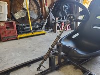
Decided to re-do the steering with the extra steering shaft I had. It's now new and improved!
20211110_142841.jpg
Still a bit more work to do on it. I have to drop the end of the shaft by drilling a new hole in the lower steering shaft support because I want to run it with the pitman arms facing upwards (have to do it that way on account of the new steering links).
20211110_142903.jpg
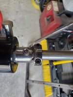
The steering wheel has been adapted to a quick-removal hub to make getting in and out easier. However, the steel part of the hub is designed to be welded on, which would prevent the steering bushings from being removable/serviceable. So instead I drilled and tapped two holes in the hub, and drilled 2 small indents in the steering shaft to give the set screws a better bite. It seems to work well, but I will definitely be using some removable thread locker just to be safe.
 

Denny

Canned Monster
Messages
11,637
Reaction score
8,074
Location
Mayberry, Indiana
I don’t see those set screws being able to hold that under a high shock load. For safety’s sake I would drill all the way through it and nut and bolt it also.
 

madprofessor

"Loose Cannon Creations"
Messages
2,899
Reaction score
962
Location
Jacksonville, Florida
For safety’s sake I would drill all the way through it and nut and bolt it also.
Absolutely ditto on full bolt-through. That's not just my OCD talking. That's the best steering setup I've ever seen anybody build, fully and easily disassembled and removed at will, and looks great too. It deserves the solidity of full-bolting.
 

SquidBonez

Active member
Messages
512
Reaction score
132
Location
New Jersey, USA
Absolutely ditto on full bolt-through. That's not just my OCD talking. That's the best steering setup I've ever seen anybody build, fully and easily disassembled and removed at will, and looks great too. It deserves the solidity of full-bolting.
Was going to originally run a bolt all the way through but A: I couldn't get it to drill a straight hole all the way through so it would be difficult to replicate on the shaft and B: I don't want to create a weak point in the shaft. I could drill the indents deeper to give it even more bite. Paired with locktite I believe it should be good enough.

EDIT: Could I tack weld a 2 piece lock collar to the hub for extra security? I would leave the bottom part of the collar unwelded so I can still remove it.
 
Last edited:

madprofessor

"Loose Cannon Creations"
Messages
2,899
Reaction score
962
Location
Jacksonville, Florida
I couldn't get it to drill a straight hole all the way through so it would be difficult to replicate on the shaft
Those indents on the shaft wouldn't line you up for a straight-through drilling that matches the holes for the setscrews? Regardless, I've done several things like that just locking everything together and drilling through everything at once. Lined up automatically.
tack weld a 2 piece lock collar to the hub
That's an outstanding idea. Half of a double-split collar welded to the hub would work great, just mount both halves of the hub and torque it down tight to the shaft before welding the one half.
 

Budget GoKart

Aka a kenbar
Messages
2,195
Reaction score
153
Location
roachdale, indiana
with the price you have so far you could have bought a parts golf kart to donate parts or modify LOL cool project though! i cant wait to see the finished result
 

SquidBonez

Active member
Messages
512
Reaction score
132
Location
New Jersey, USA
Those indents on the shaft wouldn't line you up for a straight-through drilling that matches the holes for the setscrews? Regardless, I've done several things like that just locking everything together and drilling through everything at once. Lined up automatically.

That's an outstanding idea. Half of a double-split collar welded to the hub would work great, just mount both halves of the hub and torque it down tight to the shaft before welding the one half.
Thank you, I am glad you mentioned that I should do some other form of security to the wheel because today I noticed that there is a slight amount of play just by moving the wheel back and forth - not even connected to any steering links/spindles.
with the price you have so far you could have bought a parts golf kart to donate parts or modify LOL cool project though! i cant wait to see the finished result
True, but I wanted something a fairly specific size, weight, and speed - all of which a golf cart wouldn't qualify LOL. I wanted something roughly the size of a quad that was simple/cheap to repair (all of it was built by me so all of it can be replaced by me) and handled like a mini crosskart/rally car. Also trying to keep it as far under 350 pounds (no driver) as possible. Top speed of 50mph minimum but still plenty of low end for drifting/climbing, which is why I went for a big block. Plus, I wanted something unique to me (however I have been toying with the idea of getting a rough set of plans together for anyone who wants to replicate it...that is, if anyone would be interested).
 
Last edited:

SquidBonez

Active member
Messages
512
Reaction score
132
Location
New Jersey, USA
Quick update, no pictures for now.

Decided that I'm going to create my own spindles. This will allow me to run bushings inside the spindles since most go-kart spindles you can buy online are just a piece of tube with a bolt through it and no form of lubrication/bushing/bearing. I may also try to incorporate some ackerman into the steering but it may be more trouble than it's worth in the end (after all, this is a backyard-built dune buggy, not a race car). If not I'll just run parallel steering and rely on the toe setting to give me a tiny amount of ackerman.
 
Last edited:

fuzzy

Member
Messages
19
Reaction score
31
Bonez, I follow the threads a lot, but post little. I am building a Granddaddy with my daughters and have diverged from plans a good bit to make it off road rated. From concern for strength and durability of the front end I used a kit similar to the link below (I think I found them a little cheaper than shown). My kingpin bolt goes through a piece of DOM (1.25" OD, 5/8"ID). I used a 1.125" hole saw on the drill press to cut this spindle down to length I wanted then used the grinder to open up the hole diameter to match the DOM and to get the angle I wanted. Beveled the edge of the spindle for weld penetration then had a buddy that used to be a pipe fabricator weld it out since it is probably the most critical, and least redundant, weld on the cart. This also let me get appropriate a-arm spacing a little easier. Looks like your rims are 4 on 4.

Amazon.com: SOUTHWEST WHEEL 2,000 lbs Trailer Axle Spindle with 4-4" Bolt Circle Hub : Automotive
 

SquidBonez

Active member
Messages
512
Reaction score
132
Location
New Jersey, USA
Got some pictures for you today.
20211120_151001.jpg
I welded the top piece of the locking collar to the steering wheel hub. Much better bite now, should be way safer. The set screws are still there as a backup.
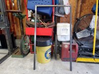
20211120_160708.jpg
Also measured and fabbed up the main roll hoop. This isn't the finished product since it will still have to be gusseted after being welded to the frame, but I wanted to get it ready.
20211120_164932.jpg
I also created custom spindles and re-made the steering links. Neither are done yet, but it should give a good idea of where they're going. These are far better than my original spindles and links since I can run bushings in them to prevent wear. Should also be way smoother as well. All four are made out of 1/4" thick steel so they should be plenty strong. Also, the holes in the spindle arms are slightly off center to provide a little bit of ackerman.
 

SquidBonez

Active member
Messages
512
Reaction score
132
Location
New Jersey, USA
Finished up the spindles and new steering links today.
20211121_150708.jpg
20211121_135043.jpg
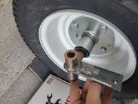
For the axle on the spindle I just used a 5/8" grade 8 bolt and welded it to the side of the spindle. Each axle has roughly 5° of negative camber (not exactly on purpose, but it will end up helping me anyway...plus the camber will be adjustable as well). The links will pivot on 5/8" bolts as well. Said bolts will be welded to the frame and will be grade 8. Pretty much every bolt I've used thus far is grade 8, especially for the steering components as they are, you know, kinda important. The next part will be making the spindle "brackets", which will actually be square tubing with heim joints to allow for camber adjustment - something very important on single a-arm designs like this.
 
Last edited:

redflash

Well-known member
Messages
650
Reaction score
625
speaking of length.......you need your knees to be comfortable for longer rides.....you don't want your knees bunched up under your chin...really uncomfortable......check first before final welding......beware of short...unless you ARE !

Da Flash
 

SquidBonez

Active member
Messages
512
Reaction score
132
Location
New Jersey, USA
speaking of length.......you need your knees to be comfortable for longer rides.....you don't want your knees bunched up under your chin...really uncomfortable......check first before final welding......beware of short...unless you ARE !

Da Flash
That was the very first thing I checked when starting this build...back when the frame was just a few pieces of tape laid out on the floor LOL. My legs are bent at a slight angle but are by no means "bunched up". It's actually pretty comfortable. The part of the frame where my legs go is 31" long, which is plenty for me even though I'm 6'1". My girlfriend has some issues though...might have to make some pedal extensions for her LOL.
 

SquidBonez

Active member
Messages
512
Reaction score
132
Location
New Jersey, USA
I got the "inboard" section of the steering together and noticed something troubling. At full lock, the steering actually binds up because the linkages are too short, causing the tie rods to push directly in on the pivot point rather than pushing the linkage around the pivot. Hard to explain through text, but this would obviously be EXTREMELY dangerous to ignore. Rest assured, I'm already fixing the problem. I have to remake the linkages (third time's a charm!). I made them roughly an inch longer on each side which solved the binding issue.
20211203_190137.jpg
20211203_192343.jpg
Everything still needs to get welded together but this should give you an idea. I plan on finishing up this part of the steering this weekend.
 

SquidBonez

Active member
Messages
512
Reaction score
132
Location
New Jersey, USA
The inboard part of the steering is now done and it works great!
20211204_162328.jpg
Lock to lock:
20211204_162334.jpg
20211204_162339.jpg
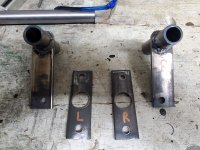
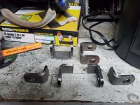
I still have plenty of clearance for my feet which was a concern I had when I made the linkages longer. I also have the suspension arm brackets ready, which are actually just go-kart spindle brackets that I cut in half.
20211204_171132.jpg
And for anyone who wants to replicate my steering design on their build, here is a full picture of the inboard part:
20211204_162533.jpg
The pivots are just 5/8" grade 8 bolts welded to the frame. The linkages themselves have bronze flange bushings so there's no wear between the bolt and the linkage itself.
 

SquidBonez

Active member
Messages
512
Reaction score
132
Location
New Jersey, USA
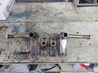
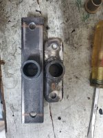
Today I began working on the front suspension arms. I didn't have much time today so all I got done was welding the suspension mounts to the frame and cutting the tubing that will be welded to the a-arms.
20211205_171829.jpg
20211205_171839.jpg
As per usual I'm using a 5/8" grade 8 bolt to attach the a-arm to the frame and bronze flange bushings to prevent wear (similar to what you would find on a Yerf Dog). The mounts themselves are super beefy. I'm unsure of the exact thickness but they are thicker than 1/4". Should be plenty strong. I can already tell that this setup will have a slight amount of bumpsteer but hopefully nothing drastic. Either way, it will be far better than if I just ran tie rods directly to the spindles. I could always modify the ends of the linkages to be closer to the pivot point of the a-arms if need be, but I think (hope) I should be fine the way it is.
 
Top