Lunar Rover (prototype)

Functional Artist

Well-known member
Messages
5,628
Reaction score
3,264
Location
Toledo, Ohio
I'm thinkin' to "muscle" this "tail" around we are gonna need some really Heavy Duty Cables :thumbsup:

I found this one on a good deal @ Surplus Center :cool: (~$2.00)
https://www.surpluscenter.com/Engin...trol-Cables/78-Steel-Control-Cable-1-3487.axd

78 INCH CONTROL CABLE
New, steel control cable. Vinyl coating on inner cable for smooth travel. Includes 3 attachment brackets on jacket. Snaps into 9/16" hole at each end.

SPECIFICATIONS •Total Length 78"
•Travel 3-3/8"
•Cable Dia. 0.15"
•Jacket O.D. 7/16"
•Connectors 3/8" dia. barrel
•Shpg. 2 lbs.


Yup, that's a 5/32 inner cable, in a 7/16" outer jacket :cheers2:
...plus, @ 78" long, if I cut 'er in 1/2
...& can get both (left & right) cables outta the (1) :2guns:

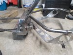
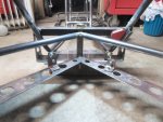
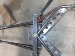
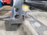
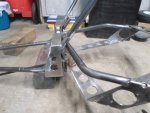
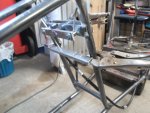
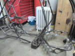
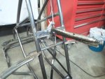
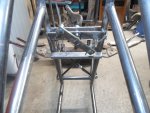
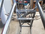
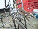
So, I did some tryin', testin' figurin' & alignin'
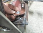
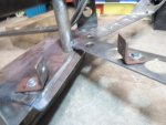
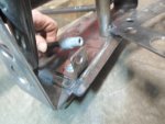
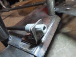
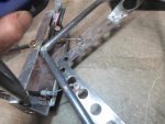
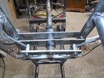
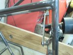
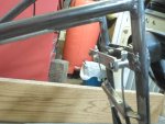
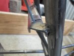
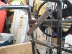
...to find an opportune position (I think, anyways) to mount the housings & pull brackets :idea2:

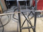
* I found that when a side is in the retracted or "closed position" the cable housing & the inner cable had to be aligned pretty well
…but, there's more "play" to work with when a side is in the extended or "open position"

** Also, I noticed that it seems to help "lubricate" the actuation/movement if the brackets are allowed to pivot or swivel a bit :wai:
 

Attachments

  • SAM_2214.JPG
    SAM_2214.JPG
    313.5 KB · Views: 2
  • SAM_2221.JPG
    SAM_2221.JPG
    318.3 KB · Views: 2
  • SAM_2222.JPG
    SAM_2222.JPG
    313.3 KB · Views: 2
  • SAM_2223.JPG
    SAM_2223.JPG
    315.6 KB · Views: 2
  • SAM_2224.JPG
    SAM_2224.JPG
    314.2 KB · Views: 3
  • SAM_2235.JPG
    SAM_2235.JPG
    315.2 KB · Views: 3
  • SAM_2234.JPG
    SAM_2234.JPG
    314.2 KB · Views: 3
  • SAM_2233.JPG
    SAM_2233.JPG
    310.3 KB · Views: 3
  • SAM_2226.JPG
    SAM_2226.JPG
    317.8 KB · Views: 2
  • SAM_2225.JPG
    SAM_2225.JPG
    313 KB · Views: 2

Functional Artist

Well-known member
Messages
5,628
Reaction score
3,264
Location
Toledo, Ohio
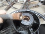
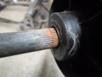
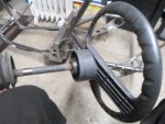
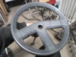
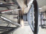
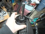
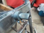
I pulled the steering shaft out of a MTD Yard Machine Riding Mower
...it has a kinda unique steering wheel too :thumbsup:

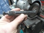
It's a standard 5/8" steel rod with splines
…that's tapped for a 5/16" retaining bolt :cheers2:
 

Attachments

  • SAM_2241.JPG
    SAM_2241.JPG
    313.8 KB · Views: 1
  • SAM_2238.JPG
    SAM_2238.JPG
    293.1 KB · Views: 1
  • SAM_2237.JPG
    SAM_2237.JPG
    323.2 KB · Views: 2
  • SAM_2236.JPG
    SAM_2236.JPG
    316.5 KB · Views: 1

5814SpeedCo

Member
Messages
150
Reaction score
8
Location
Fort Worth, TX
What kind of tubing bender do you have? I have a Harbor Freight pipe bender and anything past a 45-ish degree starts kinking my tubing. I'm using some 1-1/4" 11ga tubing. So a fairly thick wall but need to get some tighter bends.
 

itsid

Moderator
Staff member
Messages
11,563
Reaction score
247
Location
Ruhrpott [Germany]
but you are aware that this
View attachment 115586
is the wrong way around, no?
steering left would make the kart go right and vice versa...
so you'd need to cross the cables in order to correct the steering..
but cables... ah well I'll keep my fingers crossed it'll work
(not having too high hopes I'm afraid)

'sid
 

Functional Artist

Well-known member
Messages
5,628
Reaction score
3,264
Location
Toledo, Ohio
What kind of tubing bender do you have? I have a Harbor Freight pipe bender and anything past a 45-ish degree starts kinking my tubing. I'm using some 1-1/4" 11ga tubing. So a fairly thick wall but need to get some tighter bends.

I have been using a standard 8 ton HF pipe bender for years :thumbsup:

It looks like your tryin' to use a pipe bender to bend steel tube :huh:
(their 2 very different animals)

For DIY purposes, I've heard that packin' the tube with sand, helps avoid kinks :cheers2:
…& also, maybe try some type of clamp, to keep the tube from "raising up" & out of the bending die :idea2:

---------- Post added at 09:56 AM ---------- Previous post was at 09:47 AM ----------

but you are aware that this
View attachment 115586
is the wrong way around, no?
steering left would make the kart go right and vice versa...
so you'd need to cross the cables in order to correct the steering..
but cables... ah well I'll keep my fingers crossed it'll work
(not having too high hopes I'm afraid)

'sid

Yup,
...it clearly states, in the Lunar Rover Operating Manual
(Chapter 3: Controls, page 16, paragraph 2) "turn right, to go left" :roflol:

Ya gotta stay "open minded", pal :thumbsup:

I don't know if its gonna work, either :cheers2:
...but, were gonna find out, together :2guns:
 

itsid

Moderator
Staff member
Messages
11,563
Reaction score
247
Location
Ruhrpott [Germany]
well if you wanna find out feel free ;)
but the cables are tied pretty close to the pivot,
so the axle's leverage will be pretty hard to overcome once there's rubber between the kart and the road....
and assuming you also use a long lever on the steering linkage up front (as per your drawing)
it will be a massive pain to turn,
plus it'll be turning the wrong way if it at all decides to change direction..
since frankly it won't even try to swing it's behind when it's not in motion that I can almost guarantee already.

two semi-independend push levers would feel much more natural
if you do not want to cross the cables (for whatever reason that might be)
but "inversed" steering wheel is a brain fart (fun to watch, not fun to drive!)

That thing will handle crappy anyways with two solid live axles
trying hard to push straight forward (both axles should have a differential IMHO)
installing reversed steering behaviour that's also terribly hard to turn...

Ah well.. I'll keep quiet if you want;
but that thing might turn out to be just art (as in should sit stationary in a museum)
since it'll not turn out to be functional if you do not revisit your steering setup ;)

'sid
 

Functional Artist

Well-known member
Messages
5,628
Reaction score
3,264
Location
Toledo, Ohio
DIY Machine Shop

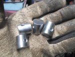
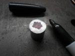
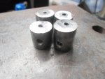
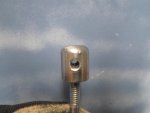
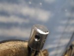
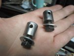
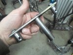
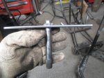
Need to make some custom, swiveling inner cable connectors
...for connecting 'em to the steering linkage bar :thumbsup:

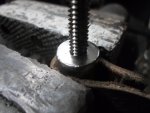
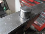
Step 1. Side Holes
Scored (installed lines not picked up :lolgoku:) a piece of 5/8" steel rod @ 1" incriments
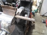
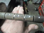
(but, otherwise left it whole for now, for grippin' purposes) :cheers2:

Then, drilled (4) 5/32" holes (right in the middle of each section
...cleaned 'em up
…& cut 'em off

Step 2. End Holes

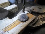
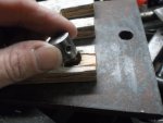
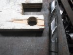
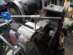
Drilled a 5/8" hole into a 1/2" thick piece of scrap plywood

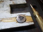
Colored a spot on the ends of the rod pieces
(makes it easier to see the marks)

Marked the center
...centered punched 'em
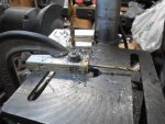
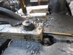
...aligned it in the drill press/clamped 'er down
…& drilled 'em out :2guns:
(just an 1/8" for now)
 

Attachments
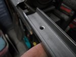
  • SAM_2313.JPG
    SAM_2313.JPG
    314.4 KB · Views: 1
  • SAM_2315.JPG
    SAM_2315.JPG
    319.7 KB · Views: 1
  • SAM_2318.JPG
    SAM_2318.JPG
    311.4 KB · Views: 1
  • SAM_2321.JPG
    SAM_2321.JPG
    316.7 KB · Views: 1
  • SAM_2345.JPG
    SAM_2345.JPG
    306.7 KB · Views: 1
  • SAM_2353.JPG
    SAM_2353.JPG
    308.2 KB · Views: 1
  • SAM_2349.JPG
    SAM_2349.JPG
    318.3 KB · Views: 1
  • SAM_2344.JPG
    SAM_2344.JPG
    311.3 KB · Views: 1
  • SAM_2341.JPG
    SAM_2341.JPG
    311.6 KB · Views: 1
  • SAM_2340.JPG
    SAM_2340.JPG
    308.9 KB · Views: 1

Functional Artist

Well-known member
Messages
5,628
Reaction score
3,264
Location
Toledo, Ohio
DIY Machine Shop cont.

Step 3. Enlarging the Holes

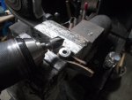
Drilled the end holes out to 17/64" (the proper size hole to tap 5/16" threads) :thumbsup:
...chamfered the inside edge of the holes (helps gettin' the tap started) :cheers2:

Step 4. Tapping the Holes
Ran a 5/16" tap thru 'em (well, most of the way thru) :2guns:
 

Attachments
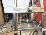
  • SAM_2356.JPG
    SAM_2356.JPG
    311.8 KB · Views: 1
  • SAM_2357.JPG
    SAM_2357.JPG
    314.3 KB · Views: 1
  • SAM_2362.JPG
    SAM_2362.JPG
    311.3 KB · Views: 1
  • SAM_2360.JPG
    SAM_2360.JPG
    314.3 KB · Views: 1
  • SAM_2363.JPG
    SAM_2363.JPG
    308.1 KB · Views: 1
  • SAM_2364.JPG
    SAM_2364.JPG
    317.5 KB · Views: 1

Functional Artist

Well-known member
Messages
5,628
Reaction score
3,264
Location
Toledo, Ohio
DIY Machine Shop conclusion

Step 5 Shaping

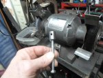
Used a 5/16" bolt, threaded into the end, as a handle
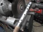
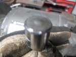
…& a bench grinder to kinda round the edges of the "top" of each piece

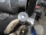
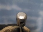
* I noticed that the tap, put a "dome", on the end of (1) of 'em :rolleyes:

Step 6. Polishing

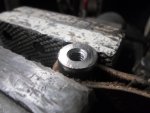
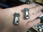
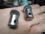
The wire brush, on the bench grinder, polished 'em up a bit
...kinda gave 'em a kool "industrial" look :2guns:
 

Attachments
  • SAM_2391.JPG
    SAM_2391.JPG
    311 KB · Views: 1
  • SAM_2385.JPG
    SAM_2385.JPG
    304.6 KB · Views: 1
  • SAM_2382.JPG
    SAM_2382.JPG
    312.8 KB · Views: 1
  • SAM_2379.JPG
    SAM_2379.JPG
    314.6 KB · Views: 2
  • SAM_2378.JPG
    SAM_2378.JPG
    311.5 KB · Views: 1
  • SAM_2392.JPG
    SAM_2392.JPG
    294.7 KB · Views: 2
  • SAM_2393.JPG
    SAM_2393.JPG
    313 KB · Views: 1
  • SAM_2394.JPG
    SAM_2394.JPG
    309.8 KB · Views: 1
  • SAM_2395.JPG
    SAM_2395.JPG
    306.4 KB · Views: 1

Functional Artist

Well-known member
Messages
5,628
Reaction score
3,264
Location
Toledo, Ohio
well if you wanna find out feel free ;)
but the cables are tied pretty close to the pivot,
so the axle's leverage will be pretty hard to overcome once there's rubber between the kart and the road....
and assuming you also use a long lever on the steering linkage up front (as per your drawing)
it will be a massive pain to turn,
plus it'll be turning the wrong way if it at all decides to change direction..
since frankly it won't even try to swing it's behind when it's not in motion that I can almost guarantee already.

two semi-independend push levers would feel much more natural
if you do not want to cross the cables (for whatever reason that might be)
but "inversed" steering wheel is a brain fart (fun to watch, not fun to drive!)

That thing will handle crappy anyways with two solid live axles
trying hard to push straight forward (both axles should have a differential IMHO)
installing reversed steering behaviour that's also terribly hard to turn...

Ah well.. I'll keep quiet if you want;
but that thing might turn out to be just art (as in should sit stationary in a museum)
since it'll not turn out to be functional if you do not revisit your steering setup ;)

'sid

Sid, I appreciate your comments (always gets me thinkin') :cool:
...so, yes please keep 'em coming :thumbsup:

I was jokin' around
...the steering will NOT operate "backwards"
...the cables can be criss-crossed quite easily :cheers2:

(from post #79)
"boat's also steer, from the rear too

Thinkin' about this, made me notice/or realize
...if ya steer from the rear, everything works backwards

So, (see pic below) if ya turn the steering wheel toward the right
...it would pull on the left side of the tail or "rudder"
(basically, closing the gap between the kart & the tail, on the left side)
…which would make the kart go or head toward the left"


But, why so serious? :huh:

I'm just experimentin' & explorin'
...NOT playin' with fire or nuthin' :lolgoku:

IMO, HD cables seem to have some potential :idea2:

I chose the rear steering cable connection location after lots of trial-n-error
…& where I put 'em seemed to be the "happy medium" :2guns:

Aren't ya interested in findin' out if (&/or) how well this thing will "function"?
...or how badly/on what level it doesn't?
…& also, what (if anything) doesn't function well? :ack2:

Don't ya think an AWD go kart that "looks" like it can "crash thru walls" would be BAD AZZ? :sifone:
...even if it "handles like a tank" (which, I'm not conceding that it will) :rolleyes:
 

itsid

Moderator
Staff member
Messages
11,563
Reaction score
247
Location
Ruhrpott [Germany]
Sid
...
But, why so serious? :huh:
Well. Sorry Kevin..
I see you putting in quite an amount of effort and some conciderable amount of money too..

I find it hard to just sit back and relax when I have the strangest feeling of you wasting that amount of efforts
especially when I think there's a way to prevent that from happening

post #76 shows the tail in a corner quite well (last pic)..
and I thought: "Well that was doodoo.. he'll see it tomorrow"
both actually.. cables and the tail wiggling thing.
I thought another two minutes of thorough thinking about it should do..
I mean we all know how clunky those wooden kids dollies steer
with 'cable steering' and they don't run a live axle on the front.
How could that get any better with live axles and serious weight on serious amounts of rubber?

With the whole cage and tube hoopla earlier I was hesitant to mention it immediately..
So I just dropped a rack and pinion in to maybe spark an idea,
just didn't want to step on your toes that hard again ;)
but after nearly a week I couldn't hold back anymore..
after you attached the cables in a place where they have very little chance of getting enough leverage over the swingarm.
and still inversed steering...
I got nervous that kart would have so many issues in the end that you loose interest in trying to fix it at all after you thought you were done.

And at that point, the then "wasted effort" seriously concerned me.

In short: I'd like to see that thing come to life and "work"

'sid
 

Functional Artist

Well-known member
Messages
5,628
Reaction score
3,264
Location
Toledo, Ohio
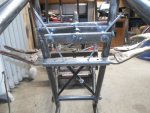
Steering Linkage (up front)

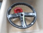
I cleaned the steering wheel up (Dawn soap, an old tooth brush & some elbow grease)
…& cleaned up & shortened the shaft too :thumbsup:

But, I'm assemblelin' a "test" shaft first
...just to see "if" this concept is gonna work :cheers2:

As, I discussed in post #80,
"The "dash" area is only ~8" wide
…& I kinda don't want the steering linkage stickin' out from the sides
(movin' parts with pinch points-n-all)

But, to stay within that 8", there would only be ~4" of "pitman arm" stickin' out from each side of the steering shaft
…& to attach, to the "tail" @ only ~4" from the pivot didn't seem like it would give us very much leverage

So, I'm thinkin', on the "tail" we gotta go a bit more (let's say at least 5 1/2")

Attaching further from the pivot point would (of course) give us more leverage
...but, that requires more "cable travel" that we really don't have available in the front

I'ma gonna give this a try
…& then, see how difficult it is to pull the cables just "by hand""


It seemed to pass this "pullin' on the cables by hand" test, pretty easily (I might add)
...so, I figured we could move on :cool:

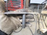
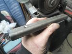
I cut an 8" piece of steel for the steering "cross bar" (this would give us ~4" of "leverage" on each side)
...but, for the "test shaft", I cut a 6" bar (this would only give us ~3" on each side)

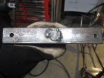
Before assembling the "test shaft", I measured, marked & drilled 1/4" holes ~1/2" from each end of the 6" bar
…& a 5/8" hole in the center
...then, squared 'em up & tac welded 'em together

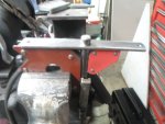
Also, made a cable housing mount/retainer bracket for up front
...some 1" C-channel seemed to work well (just added some ~3/16" holes :2guns:
 

Attachments

  • SAM_2291.JPG
    SAM_2291.JPG
    318.1 KB · Views: 1
  • SAM_2287.JPG
    SAM_2287.JPG
    315.6 KB · Views: 1
  • SAM_2285.JPG
    SAM_2285.JPG
    312.9 KB · Views: 1
  • SAM_2281.JPG
    SAM_2281.JPG
    312 KB · Views: 1
  • SAM_2279.JPG
    SAM_2279.JPG
    312.2 KB · Views: 1
  • SAM_2304.JPG
    SAM_2304.JPG
    320.2 KB · Views: 1
  • SAM_2303.JPG
    SAM_2303.JPG
    317 KB · Views: 1
  • SAM_2327.JPG
    SAM_2327.JPG
    319.1 KB · Views: 1
  • SAM_2329.JPG
    SAM_2329.JPG
    316.2 KB · Views: 1
  • SAM_2335.JPG
    SAM_2335.JPG
    321.8 KB · Views: 1

Functional Artist

Well-known member
Messages
5,628
Reaction score
3,264
Location
Toledo, Ohio
I tried criss-crossing the cables several different ways :thumbsup:

Crossin' them, up in front of the lower dash area seemed to work out better than under the seat

Slid the inner cable wire thru the cable housing bracket (C-channel)
…& also, thru the custom, swiveling inner cable connectors (mounted to the steering cross bar)

* Criss-crossin' the cables even seems to assist the "entry angle"
...of where the cables connect to the steering bar & the way they rotate or "swing" :2guns:
 

Attachments

  • SAM_2325.JPG
    SAM_2325.JPG
    315.9 KB · Views: 1
  • SAM_2324.JPG
    SAM_2324.JPG
    319.2 KB · Views: 1
  • SAM_2323.JPG
    SAM_2323.JPG
    314.2 KB · Views: 1
  • SAM_2332.JPG
    SAM_2332.JPG
    314 KB · Views: 1
  • SAM_2333.JPG
    SAM_2333.JPG
    313.8 KB · Views: 1
  • SAM_2334.JPG
    SAM_2334.JPG
    319.7 KB · Views: 1
  • SAM_2401.JPG
    SAM_2401.JPG
    315.1 KB · Views: 1
  • SAM_2400.JPG
    SAM_2400.JPG
    315.4 KB · Views: 1
  • SAM_2397.JPG
    SAM_2397.JPG
    316.2 KB · Views: 1
  • SAM_2402.JPG
    SAM_2402.JPG
    318.7 KB · Views: 1

Functional Artist

Well-known member
Messages
5,628
Reaction score
3,264
Location
Toledo, Ohio
6" Cross Bar Steering Assembly Test

I just clamped a pair of ViceGrips onto the stub stickin' out of the "test steering shaft"
…& gave 'er a twist, with just (1) hand (it wasn't that difficult to turn) :wai:

Here is a quick video documenting this 6" cross bar test :thumbsup:

https://www.youtube.com/watch?v=RvbPnJaUnng
 

Attachments

  • SAM_2403.JPG
    SAM_2403.JPG
    314.4 KB · Views: 1
  • SAM_2405.JPG
    SAM_2405.JPG
    317.1 KB · Views: 1
  • SAM_2409.JPG
    SAM_2409.JPG
    316 KB · Views: 1
  • SAM_2408.JPG
    SAM_2408.JPG
    313.9 KB · Views: 2
  • SAM_2407.JPG
    SAM_2407.JPG
    316.4 KB · Views: 1
  • SAM_2404.JPG
    SAM_2404.JPG
    314.5 KB · Views: 1
  • SAM_2406.JPG
    SAM_2406.JPG
    313.4 KB · Views: 1

Functional Artist

Well-known member
Messages
5,628
Reaction score
3,264
Location
Toledo, Ohio
Well. Sorry Kevin..
I see you putting in quite an amount of effort and some conciderable amount of money too..

I find it hard to just sit back and relax when I have the strangest feeling of you wasting that amount of efforts
especially when I think there's a way to prevent that from happening

post #76 shows the tail in a corner quite well (last pic)..
and I thought: "Well that was doodoo.. he'll see it tomorrow"
both actually.. cables and the tail wiggling thing.
I thought another two minutes of thorough thinking about it should do..
I mean we all know how clunky those wooden kids dollies steer
with 'cable steering' and they don't run a live axle on the front.
How could that get any better
With the whole cage and tube hoopla earlier I was hesitant to mention it immediately..
So I just dropped a rack and pinion in to maybe spark an idea,
just didn't want to step on your toes that hard again ;)
but after nearly a week I couldn't hold back anymore..
after you attached the cables in a place where they have very little chance of getting enough leverage over the swingarm.
and still inversed steering...
I got nervous that kart would have so many issues in the end that you loose interest in trying to fix it at all after you thought you were done.

And at that point, the then "wasted effort" seriously concerned me.

In short: I'd like to see that thing come to life and "work"

'sid

Sorry Alex, I'm really NOT tryin' to get ya "shook"
…& I also, really appreciate ALL of your input & concern :thumbsup:

I guess I have "issues" with gettin' something outta my head
...until I find out/figure it out for myself

During my research on articulated steering vehicles, it seemed like the steering on most "wheeled vehicles" was hydraulically actuated (not really doable on a kart)
...but, most of them were big, giant, huge machines so, I could understand the need for a super heavy duty & powerful steering action.

Many airplanes & boat have rear steering & it's usually cable actuated
(granted they do NOT have to deal with "live axles and serious weight on serious amounts of rubber") :huh:
...but, were talkin' about a kart that should only weigh a couple of hundred pounds

* If ya think about it, the Rovers "tail" operates kinda like an outboard motor on a speed boat
...& provides both propulsion & steering :cool:

I also thought about using levers & rods to actuate the steering
...but, it seemed like "overkill" on a go kart (still may be an option)

Another thing that I've noticed, over the years, is that most "actions" (shifting gears, activating the blades etc.) on riding lawn mowers used to be actuated by rods & levers
...but, anymore most of these things are cable actuated (little dinky ~1/16" cables)

So, I figured if were even gonna try-n-use cables, to steer this thing, they have to be kinda heavy duty
…& the cables, that I'm using, are almost 3/16" thick (pretty strong stuff, I must say) :2guns:

FYI:
1. So, far this project consists of only ~$50.00 in steel

2. The main frame is not crooked, (within at least ~1/4") it must be an optical illusion in the pic

3. The "upper frame" parts/pipes only adds ~ 28lbs.
..."hood" ~6' of pipe, ~3' on each side (~6lbs.)
...the "roll cage" adds ~ 14', ~7' on each side (~14lbs.)
...& the "tail cage" adds ~8', ~4' on each side (~8lbs.)
...but, it adds a "whole lot of style" :sifone:

4. I agree differentials would be ideal
...but, they would add at least $200.00 to the build ticket (could be added later, if set up properly)

I think it's coming along nicely
...but, we'll see, you may be right (like you have been many, many times) :cheers2:
 

Functional Artist

Well-known member
Messages
5,628
Reaction score
3,264
Location
Toledo, Ohio
Trying an 8" cross-bar on the steering shaft

The connection points on the steering cross-bars are ~1/2" from the ends.

So, it's ~2 1/2" from the center pivot point to each of the connection points on the (6") "test steering shaft"
…& the connection points, on the "tail", were ~5 1/2" from it's center pivot point.

Now, as per Sid's concern's, :cheers2: I've been tryin' to gain a bit more leverage :thumbsup:

So, I made an 8" cross-bar for the steering shaft (now, the pivot point to connection point is ~3 1/2")
…& I moved the connection points "out" a few inches, on the "tail" too.
(so, now, the pivot point to the connection point is ~8 1/2") :2guns:

Version 1.
...6" cross-bar (2 1/2" front by 5 1/2" rear)
Version 2.
...8" cross-bar (3 1/2" front by 8 1/2" rear)

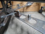
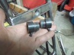
* I also, tried a couple of the "DIY machine shop" connectors, that I made up, instead of the "L" brackets, that I tried previously.

The lower & more direct connection point seemed to be beneficial
...& they still swivel ;)

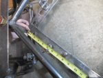
** The last pic kinda shows the difference in "travel" pretty well
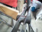
...but, after testing, using the inner bracket mounting point, on the main frame, seemed to work out better. :)
 

Attachments

  • SAM_2443.JPG
    SAM_2443.JPG
    319.8 KB · Views: 1
  • SAM_2434.JPG
    SAM_2434.JPG
    313.1 KB · Views: 0
  • SAM_2429.JPG
    SAM_2429.JPG
    319.3 KB · Views: 0
  • SAM_2431.JPG
    SAM_2431.JPG
    310.5 KB · Views: 1

itsid

Moderator
Staff member
Messages
11,563
Reaction score
247
Location
Ruhrpott [Germany]
I think you still misunderstood ... :(

you need the SHORTEST possible distance up front
(cable attached as close to the steering shaft as possible)
and the LONGEST possible distance at the back
(cable attached the furthest from the pivot of the swingarm)

not short short or long long..
that's not making much of a difference at all
(5.5/2.5 is a 2.2 advantage; 8.5/3.5 is a 2.4 advantage aka very little gain)
if instead you get 8.5 at the back and 2.5 up front you actually increase to 3.4
which would be at least an improvement.

BUT it's NOT 5.5 nor would it be 8.5 at all
it's ~3.5 or such
so no noteworthy advantage at all I'm afraid. (1.4 at best)
in order to make it "bigger" you'd need a halfmoon (with 5.5" or 8.5" radius)
for the cable to attach to.

Have I mentioned that a rack and pinion would be way easier? ;)


'sid
 

Functional Artist

Well-known member
Messages
5,628
Reaction score
3,264
Location
Toledo, Ohio
I squared up & welded the 8" steering cross-bar to the splined shaft :thumbsup:
…& added a piece of pipe between the "dash bars" to strengthen this junction

Trimmed the cable housing retainer up a bit
...added some "slots"
…& then, welded 'er on :cheers2:

Also, installed the cables with the factory retainer in the front this time (to help "clean up" this area) :2guns:

Here is a video of The Rover's "Tail Waggin' the Dog " :lolgoku:
...mechanical "poetry in motion" :cool:

https://www.youtube.com/watch?v=heR3_SOBusg
 

Attachments

  • SAM_2479.JPG
    SAM_2479.JPG
    318.6 KB · Views: 1
  • SAM_2478.JPG
    SAM_2478.JPG
    314.3 KB · Views: 2
  • SAM_2474.JPG
    SAM_2474.JPG
    311.5 KB · Views: 1
  • SAM_2470.JPG
    SAM_2470.JPG
    315.5 KB · Views: 1
  • SAM_2467.JPG
    SAM_2467.JPG
    317.4 KB · Views: 1
  • SAM_2483.JPG
    SAM_2483.JPG
    316.6 KB · Views: 1
  • SAM_2488.JPG
    SAM_2488.JPG
    311.2 KB · Views: 1
  • SAM_2491.JPG
    SAM_2491.JPG
    311 KB · Views: 1
  • SAM_2498.JPG
    SAM_2498.JPG
    314.7 KB · Views: 1
  • SAM_2496.JPG
    SAM_2496.JPG
    314 KB · Views: 1

Functional Artist

Well-known member
Messages
5,628
Reaction score
3,264
Location
Toledo, Ohio
I think you still misunderstood ... :(

you need the SHORTEST possible distance up front
(cable attached as close to the steering shaft as possible)
and the LONGEST possible distance at the back
(cable attached the furthest from the pivot of the swingarm)

not short short or long long..
that's not making much of a difference at all
(5.5/2.5 is a 2.2 advantage; 8.5/3.5 is a 2.4 advantage aka very little gain)
if instead you get 8.5 at the back and 2.5 up front you actually increase to 3.4
which would be at least an improvement.

BUT it's NOT 5.5 nor would it be 8.5 at all
it's ~3.5 or such
so no noteworthy advantage at all I'm afraid. (1.4 at best)
in order to make it "bigger" you'd need a halfmoon (with 5.5" or 8.5" radius)
for the cable to attach to.

Have I mentioned that a rack and pinion would be way easier? ;)


'sid

Post #76 I asked
"Workin' on controlin' the "tail"

1.) How far should it swing?
...is there a "too far"?

2.) Is there a proper or necessary distance from the pivot point to the where the steering linkage will connect?
…& on the other end, how do ya figure the proper distance from the steering wheel pivot point to where the steering linkage will connect?

3.) Would it be best for them to be the same?
...or to maybe have the steering end a bit longer, for additional leverage?"


Your reply
"cable pull .. I somehow assumed a rack and pinion steering tbh
with a "drive" shaft going to the back and acting on the swingarm directly"


Total design change? :huh:

Then, post #87 you mention
"but the cables are tied pretty close to the pivot,
so the axle's leverage will be pretty hard to overcome once there's rubber between the kart and the road....
and assuming you also use a long lever on the steering linkage up front (as per your drawing)
it will be a massive pain to turn"

…& post #92 "you attached the cables in a place where they have very little chance of getting enough leverage over the swingarm"

So, I take your advise & work to "gain a bit more leverage"

Now, you reply "I think you still misunderstood" :mad2:
…& "Have I mentioned that a rack and pinion would be way easier?"

* So, is it the main frame vs. the tail
...or the kart vs. the ground
...or both?

** I guess, please "draw me a picture" of this "rack & pinion" that you have in mind :cheers2:
 
Top