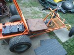
El Turbo Need a 50A fuse?

Status
Not open for further replies.

itsid

Moderator
Staff member
Messages
11,563
Reaction score
248
Location
Ruhrpott [Germany]
You start off with a BRILLIANT idea :thumbsup: "twin fuses"

...& even suggest: "make your own two fuse holder from scratch as per your needs (to match your fuses)"

I'm thinkin', kool now we're gettin' somewhere

So, I ask, what do you have in mind?

Your response: "IDK what you want me to explain really..."


Uh, how about the vague suggestion you just made


as I said, I never saw or heard of a dual fuse holder

Then, you go into a "picture this" type description, with out any pictures, diagrams or anything (which you dislike)

& then end with

"If I find a piece of tubing somewhere I can mock one up if you like or sketch it out (but frankly I cannot imagine why you would need that really)"

*I'm NOT asking you to hold my hand thru the whole build

I just didn't understand what you had in mind

Yes, I walked away from the computer SMH (shakin' my head) :ack2:

*I AM NOT LOOKING TO SPAR WITH YOU

I tell my wife about the great ideas "my friend" Sid helps me with ALL the time

Some... no, most times your SUPER helpful

...other times well lets just say, you seem kinda moody (maybe a German thing IDK) :cornut:

I just wanted to let you know how I felt

moody.. may be.. may very well be :D

but this is more a comprehensive issue...
I just didn't understand that you were asking for a sketch or alike.

I tend to write obnoxiously long posts, especially when I have the feeling whoever I'm responding to could use as much details as possible (for whatever reason ;))
that "but frankly I cannot imagine why you would need that really"
I said because I'm rather confident you do not fall in most of those "use cases"
you know your stuff pretty well, you know how to help yourself most of the time; and so I keep my responses shorter ;)

But you asked for it.. so here we go:
I couldn't find any tubing that fits my bill;
and frankly my trusted vector graphics tool left me without proper coloring/shading; so hand drawn black and white .. sorry.. it's a sketch

I tried to explain how I'd go for that earlier,
so I reuse some of that and just add a picture ;)
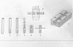
fuseholder_sketch.png
grid is 5 by 5 mm and only a "rough" guide
  1. cut a single slot half an inch long in one end
    now thinking of it, a relief cut might make it easier to clamp the wire afterwards... in any case a hose clamp (or similar) should be able to fix the wire to said tube
  2. cut two slots starting ~ 1/4" (or 5/8") above the first all the way through
  3. flatten the tube in your bench vise so you end up with two strips
    use a 5mm OD rod inserted into the tube to prevent the tube from collapsing on the lower part.
  4. fold the flat strips over to create just enough room for the fuse lugs to fit
  5. tighten the fold onto the lugs (vise) and use the overhang to create some tabs in a 90° angle
  6. make second identical part and testfit the two fuses.
  7. you can file and grind the parts for a nicer shape
    use those tabs to fix the two halves in a wooden block (with matching cutouts of course)
    then fix everything in place with hotglue (or epoxy if you like)

'sid
 

Functional Artist

Well-known member
Messages
5,654
Reaction score
3,293
Location
Toledo, Ohio
moody.. may be.. may very well be :D

but this is more a comprehensive issue...
I just didn't understand that you were asking for a sketch or alike.

I tend to write obnoxiously long posts, especially when I have the feeling whoever I'm responding to could use as much details as possible (for whatever reason ;))
that "but frankly I cannot imagine why you would need that really"
I said because I'm rather confident you do not fall in most of those "use cases"
you know your stuff pretty well, you know how to help yourself most of the time; and so I keep my responses shorter ;)

But you asked for it.. so here we go:
I couldn't find any tubing that fits my bill;
and frankly my trusted vector graphics tool left me without proper coloring/shading; so hand drawn black and white .. sorry.. it's a sketch

I tried to explain how I'd go for that earlier,
so I reuse some of that and just add a picture ;)
View attachment 87294
grid is 5 by 5 mm and only a "rough" guide
  1. cut a single slot half an inch long in one end
    now thinking of it, a relief cut might make it easier to clamp the wire afterwards... in any case a hose clamp (or similar) should be able to fix the wire to said tube
  2. cut two slots starting ~ 1/4" (or 5/8") above the first all the way through
  3. flatten the tube in your bench vise so you end up with two strips
    use a 5mm OD rod inserted into the tube to prevent the tube from collapsing on the lower part.
  4. fold the flat strips over to create just enough room for the fuse lugs to fit
  5. tighten the fold onto the lugs (vise) and use the overhang to create some tabs in a 90° angle
  6. make second identical part and testfit the two fuses.
  7. you can file and grind the parts for a nicer shape
    use those tabs to fix the two halves in a wooden block (with matching cutouts of course)
    then fix everything in place with hotglue (or epoxy if you like)

'sid

I like it! :thumbsup:

You start off with a BRILLIANT idea & top it off with "kool" graphic art :2guns:

...& now the forum is better off too

...we got descriptive & graphic art documentation of how to DIY a "twin fuse holder" Sid style :cornut:

...& of course, once I understood the concept

I ran with your idea & did a DIY "dual fuse holder" with my own little artistic twist

So, thanks again :cheers2:


What's your thoughts on the Turbo tests?
 

itsid

Moderator
Staff member
Messages
11,563
Reaction score
248
Location
Ruhrpott [Germany]
Wow, nice job Sid!
Since you used graph paper, would that make you a graphic artist?

I think so.. but most of it is too graphical for this forum ;)

I like it! :thumbsup:
.....
So, thanks again :cheers2:
What's your thoughts on the Turbo tests?
thank you,
but that's far from art .. it's "depiction" ;)
Anyways, if it helps it'll suffice.

Turbo test...
It seems to work well in the video,
I have some minor concerns about the back EMF of the second motor
frying the controller over time but that's neglectable since
I guess you'd have to backdrive the motor for several hours before it has a noteworthy effect

'sid
 

Functional Artist

Well-known member
Messages
5,654
Reaction score
3,293
Location
Toledo, Ohio
moody.. may be.. may very well be :D

but this is more a comprehensive issue...
I just didn't understand that you were asking for a sketch or alike.

I tend to write obnoxiously long posts, especially when I have the feeling whoever I'm responding to could use as much details as possible (for whatever reason ;))
that "but frankly I cannot imagine why you would need that really"
I said because I'm rather confident you do not fall in most of those "use cases"
you know your stuff pretty well, you know how to help yourself most of the time; and so I keep my responses shorter ;)

But you asked for it.. so here we go:
I couldn't find any tubing that fits my bill;
and frankly my trusted vector graphics tool left me without proper coloring/shading; so hand drawn black and white .. sorry.. it's a sketch

I tried to explain how I'd go for that earlier,
so I reuse some of that and just add a picture ;)
View attachment 87294
grid is 5 by 5 mm and only a "rough" guide
  1. cut a single slot half an inch long in one end
    now thinking of it, a relief cut might make it easier to clamp the wire afterwards... in any case a hose clamp (or similar) should be able to fix the wire to said tube
  2. cut two slots starting ~ 1/4" (or 5/8") above the first all the way through
  3. flatten the tube in your bench vise so you end up with two strips
    use a 5mm OD rod inserted into the tube to prevent the tube from collapsing on the lower part.
  4. fold the flat strips over to create just enough room for the fuse lugs to fit
  5. tighten the fold onto the lugs (vise) and use the overhang to create some tabs in a 90° angle
  6. make second identical part and testfit the two fuses.
  7. you can file and grind the parts for a nicer shape
    use those tabs to fix the two halves in a wooden block (with matching cutouts of course)
    then fix everything in place with hotglue (or epoxy if you like)

'sid


Yes, it helps tremendously

...quite different than the vision that first popped into my head

...that's why I asked "what do you have in mind"

...part of it was clear & part I wasn't sure about


So, thanks again, for taking the time

Very much appreciated :cornut:


It's "functional art" :thumbsup:

...pure & simple :2guns:

...looks kool & does something :cheers2:


* If that depiction was in DaVinci's note book...

Yup! "priceless" functional art
 

Functional Artist

Well-known member
Messages
5,654
Reaction score
3,293
Location
Toledo, Ohio
Can anyone "sid" explain to the class what this data tells us?

This kart would easily do 15 mph before these tests

...now 13 mph is about top speed

The first test

...regular mode top speed was 15 mph & with Turbo it went to 20 mph

...power draw for regular mode was ~32A & with Turbo went as high as 103A (consistent amp draw readings were in the 50's & peak was in the 90's)

After a couple of test runs (Turbo was engaged several times)

...regular mode top speed is ~13 mph & with Turbo only goes to ~17 mph


* I even noticed, during the third Turbo engagement, the amp draw was running ~50-60A then suddenly dropped down into the 30's
 

Attachments

  • SAM_4445.jpg
    SAM_4445.jpg
    353.2 KB · Views: 2

itsid

Moderator
Staff member
Messages
11,563
Reaction score
248
Location
Ruhrpott [Germany]
Hmm.. frankly to me that sounds like you fried one of the power mosfets in a controller.

a common size for them is 20A ... soooo loosing 20 Amps might be the telltale sign here.
but I cannot completely rule out what Joe said either I'm afraid...
could be one cell in one battery melted down for some odd reason.

disconnect the batteries and charge then measure them individually
(13.5Volts or better should be read) and all should be fairly level..

if those are sound and there's no anomalie ...
check the controllers,
IDK which one you used here, but most if not all can be opened up to peak inside.
the power mosfets are bolted to a heat sink (should be at least)
black thumbnail sized with a drilled (and hopefully bolted to said heat sink) metal tab...
take a pic of them and let me see...

'sid
 
Last edited:

itsid

Moderator
Staff member
Messages
11,563
Reaction score
248
Location
Ruhrpott [Germany]
Is that what they call them over there?
Here in the Trump of A, we call them heat sinks. :D
heat sink.. yes ty.. sometimes ...
Funny enough.. we call them both cooler (Kühler.. as in kühl = cool)
not matter if bottle or electronics... only if it's a box we call em Kühlbox...
And as that wasn't confusing enough, I look around and see Coolermaster CPU cooler and ARCTIC VGA cooler and
yeah I forgot you technically call them heat sinks. (corrected)

'sid
 

Bbqjoe

Banned
Messages
3,455
Reaction score
67
Location
Location, Location
heat sink.. yes ty.. sometimes ...
Funny enough.. we call them both cooler (Kühler.. as in kühl = cool)
not matter if bottle or electronics... only if it's a box we call em Kühlbox...
And as that wasn't confusing enough, I look around and see Coolermaster CPU cooler and ARCTIC VGA cooler and
yeah I forgot you technically call them heat sinks. (corrected)

'sid

Aw he11, I wasn't out to correct nobody! :D
 
Status
Not open for further replies.
Top