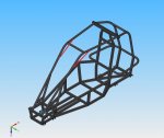
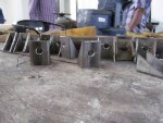
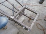
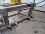
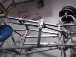
Off road buggy ...

Status
Not open for further replies.

rvndraju

New member
Messages
63
Reaction score
0
Location
india (bangalore)
I am really impressed with the progress you made so far.

I do have to agree with the safety goggles, it only takes one little peace of steel, or a broken disc for that matter to ruin someones life!!

A recommendation on the roll cage construction, to weld in additional supports to cross brace the " diamond shape. Keep into consideration that if, and when the buggy rolls, the entire weight of the frame, engine, driver and additional momentum will be exerted on the frame...:oops:

Thanks for the suggestion but when we analysed the frame using NASTRAN for various loads like 4G, 5G and 7G on the roll-cage, side impact member & front impact it proved that the frame is pretty safe. And also according to SAE BAJA rule book the driver should be abe to get out of the vehicle in 5 seconds as soon as he turns of the engine so if i put that member it would be an obstacle from the driver to get down during an accident or fire.

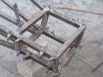
instead we have planned to weld a member like this
 

Attachments

  • iso2.jpg
    iso2.jpg
    136.5 KB · Views: 6
  • side2.jpg
    side2.jpg
    76.5 KB · Views: 2

rvndraju

New member
Messages
63
Reaction score
0
Location
india (bangalore)
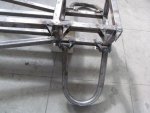
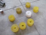
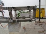
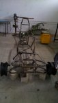
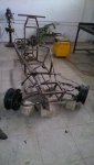
Suspension mounts on the chassis has been completed & polyurethane bushing for the A-Arms was machined from the PU rod.
 

Attachments

  • IMG_1888.jpg
    IMG_1888.jpg
    91.2 KB · Views: 15
  • IMG_1889.jpg
    IMG_1889.jpg
    104.1 KB · Views: 14
  • IMG_1917.jpg
    IMG_1917.jpg
    88.5 KB · Views: 11
  • IMG_1919.jpg
    IMG_1919.jpg
    67.4 KB · Views: 12
  • IMG_1920.jpg
    IMG_1920.jpg
    92.2 KB · Views: 14
  • IMG_1929.jpg
    IMG_1929.jpg
    87.1 KB · Views: 19
  • IMG_1928.jpg
    IMG_1928.jpg
    84.5 KB · Views: 14
  • IMG_1943.jpg
    IMG_1943.jpg
    72.3 KB · Views: 14
  • IMG_1918.jpg
    IMG_1918.jpg
    73.4 KB · Views: 15
Last edited by a moderator:

rvndraju

New member
Messages
63
Reaction score
0
Location
india (bangalore)
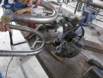
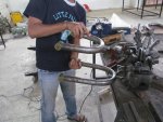
Welding Ball joint mount on to the A-Arm's. Ball joints are from Maruthi suzuki 800.
 

Attachments

  • MVI_1956.MOV_snapshot_00.25_[2014.03.21_20.35.17].jpg
    MVI_1956.MOV_snapshot_00.25_[2014.03.21_20.35.17].jpg
    42 KB · Views: 20
  • MVI_1956.MOV_snapshot_00.42_[2014.03.21_20.35.35].jpg
    MVI_1956.MOV_snapshot_00.42_[2014.03.21_20.35.35].jpg
    33.9 KB · Views: 17
  • MVI_1956.MOV_snapshot_00.51_[2014.03.21_20.35.43].jpg
    MVI_1956.MOV_snapshot_00.51_[2014.03.21_20.35.43].jpg
    37.4 KB · Views: 17

rvndraju

New member
Messages
63
Reaction score
0
Location
india (bangalore)
shopping :)

Mean while we went to buy lot of parts from shivajinagar scrap yard where we buy most of the parts for project. It was a big shopping day. the day we went there they where scrapping a maruthi suzuki 800 like the whole car was equally cut into to halves and all the mechanical parts where being removed.

List of parts brought:-

-CV joints right & left Original from Delphi (maruthi suzuki 800) $17
-Steering column (maruthi suzuki 800) $12

-steering knuckle & disc brakes $70
we actually got the full set with disc, calipers, wheel hub & steering knuckle(maruthi suzuki 800)

-Rims(4nos) (12inch, also of maruthi 800) $20

-paddle set (maruthi 800) $3
clutch, brake and throttle pedals

-tie rods 6 nos (maruthi 800) $12

-ball joint (maruthi 800) $10

-rack & pinion (Force minidor) $12

-shock absorber (front) (hero honda HUNK rear) $8

-gear lever (maruthi 800) $1

-master cylinder (maruthi 800) $2

-shock absorber(rear) (maruthi 800) $20

-steering wheel (force minidor) $2

the above was our price which we gave the shop guy, Guess how much he put in his bill before the bargain ???

$317/- :smiley_omg: . But we had a contact of my tenant, he is having a car spare shop so we knew the actual price and we where able to bargain & bring down the price to $189/-

I felt it was a good bargain though. We stuffed all the parts into my Hyundai i-20 boot thank god i-20 had a pretty good boot space or else we should have rented a small goods carrier who would have charge $15. And headed straight to collage to unload everything. :thumbsup:
 

rvndraju

New member
Messages
63
Reaction score
0
Location
india (bangalore)
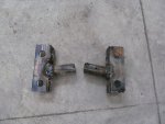
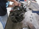
Here comes the problem, Maruthi 800 front suspension is a mcpherson strut with coil spring setup but for our requirement the steering knuckle has to be modified to accommodate Double Wishbone suspension. so we modified the lower shock mounts to some thing like this. This is a custom made part for mounting of upper arm ball joint. :thumbsup:
 

Attachments

  • IMG_1885.jpg
    IMG_1885.jpg
    101.4 KB · Views: 11

rvndraju

New member
Messages
63
Reaction score
0
Location
india (bangalore)
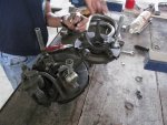
Finally after fastening the custom mount on to the knuckle we where able to mount upper and lower arm on the wheel hub assembly successfully. :wai:
 

Attachments

  • IMG_1951.jpg
    IMG_1951.jpg
    109 KB · Views: 25
  • IMG_1952.jpg
    IMG_1952.jpg
    113.6 KB · Views: 23
  • IMG_1955.jpg
    IMG_1955.jpg
    112.8 KB · Views: 30
  • 1337938349_384271969_1-Pictures-of--G-Force-Baleka-Off-Road-Buggy.jpg
    1337938349_384271969_1-Pictures-of--G-Force-Baleka-Off-Road-Buggy.jpg
    109.5 KB · Views: 33

DMCdesign

Master Apprentice
Messages
275
Reaction score
0
Location
Uttrakhand, India
I had said right about famous car scrapyards

you look pretty good on budget! how much have you spent in it in overall? (in rupees)

just keep on going and you'll be riding it!
 

rvndraju

New member
Messages
63
Reaction score
0
Location
india (bangalore)
I had said right about famous car scrapyards

you look pretty good on budget! how much have you spent in it in overall? (in rupees)

just keep on going and you'll be riding it!

our budget is Rs. 45,000 ($750) & till today we have spent around Rs. 35,000 ($580). Still we got to buy tyres, seat, brake lines, Paint & some other small accessories. Hope we complete within the budget :) :popcorn:
 

rvndraju

New member
Messages
63
Reaction score
0
Location
india (bangalore)
Then came the challenging part where we had to transfer all the dimensions of the front suspension into the software ( suspension analyser V2.4) where we optimized the front end to minimize bump steer. And after the optimizing was done the optimized dimensions was later applied on the vehicle.

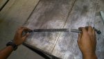
the Rack and pinion which we had brought was from "FORCE MINIDOR" (A three wheel light commercial vehicle) which had to be modified to suite our requirement. The rack was cut and welded to make it symmetric and two bolts where welded on both sides for mounting tie rods. And also two Nylon bushes where machined and mounted on both sides of the casing to reduce rack play

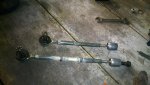
tie rods where also short so we extended it by welding an extension rod in the middle and increased the length

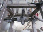
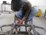
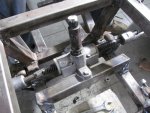
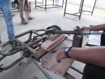
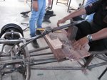
The important parameter to reduce bump steer is to place the rack and pinion assembly on the chassis exactly according to the dimensions given by the software for that we cut ply wood pieces according to the dimension and placed the R&P assembly on it and bolted it to the chassis. :wai:
 

Attachments

  • DSC_0109.jpg
    DSC_0109.jpg
    94.9 KB · Views: 11
  • rack mod.jpg
    rack mod.jpg
    77.3 KB · Views: 11

rvndraju

New member
Messages
63
Reaction score
0
Location
india (bangalore)
Rack & pinion mounting
 

Attachments

  • IMG_1970.jpg
    IMG_1970.jpg
    104.5 KB · Views: 18
  • IMG_1969.jpg
    IMG_1969.jpg
    106.8 KB · Views: 20
  • IMG_1967.jpg
    IMG_1967.jpg
    103.4 KB · Views: 18
  • IMG_1962.jpg
    IMG_1962.jpg
    87.6 KB · Views: 17
  • IMG_1959.jpg
    IMG_1959.jpg
    92.5 KB · Views: 19
  • IMG_1972.jpg
    IMG_1972.jpg
    109.5 KB · Views: 16

rvndraju

New member
Messages
63
Reaction score
0
Location
india (bangalore)
Steering column mounting

Sine the rack & pinion mounting and front suspension was almost complete we moved on to mounting the steering column. The steering column was not a direct fit with the rack & pinion because both are from two different vehicle so we had to machine the pinion end to reduce the diameter so that it can be fit into the steering yoke.
 

Attachments

  • IMG_1990 (Medium).jpg
    IMG_1990 (Medium).jpg
    67.8 KB · Views: 10
  • IMG_1989 (Medium).jpg
    IMG_1989 (Medium).jpg
    92.7 KB · Views: 10
  • IMG_1987 (Medium).jpg
    IMG_1987 (Medium).jpg
    91.5 KB · Views: 10
  • IMG_1986 (Medium).jpg
    IMG_1986 (Medium).jpg
    88.6 KB · Views: 12
  • IMG_1985 (Medium).jpg
    IMG_1985 (Medium).jpg
    94.9 KB · Views: 15
  • IMG_1993 (Medium).jpg
    IMG_1993 (Medium).jpg
    81.7 KB · Views: 13
  • IMG_1995 (Medium).jpg
    IMG_1995 (Medium).jpg
    90.7 KB · Views: 8
  • IMG_1996 (Medium).jpg
    IMG_1996 (Medium).jpg
    87.6 KB · Views: 23
  • IMG_1997 (Medium).jpg
    IMG_1997 (Medium).jpg
    78.4 KB · Views: 17
  • IMG_1999 (Medium).jpg
    IMG_1999 (Medium).jpg
    78.4 KB · Views: 18

OzFab

Well-known member
Messages
15,615
Reaction score
67
Location
Warwick Qld, Australia
Just a quick observation, wouldn't you be better off if the steering pinion went between the two front rails instead of over them? By rotating the rack backwards by about 45°, the steering column would be almost straight & would be protected by the front rails.

It's clear in pic #8 that there is still plenty of room for the pedals if the steering column runs between them, not to mention the steering wheel will be higher without raising the rear-most support...
 

firemanjim

Just kartin' around....
Messages
5,247
Reaction score
86
Location
Houston Texas
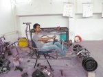
:iagree: But the driver will be sitting lower than as pictured. He is too high. His button needs to be a lot closer to the floor.... He could be thrown out of the buggy with a good side impact (some people forget to use seat belts, like welding hoods and such.... ) and that would just blow.... Lower seat position offers better driver comfort. Should have done the seat BEFORE putting pedals in final position. They go hand in hand...... :thumbsup:
Edit..... Actually, should have done the seat,pedals and steering at the same time......
 

rvndraju

New member
Messages
63
Reaction score
0
Location
india (bangalore)
Just a quick observation, wouldn't you be better off if the steering pinion went between the two front rails instead of over them? By rotating the rack backwards by about 45°, the steering column would be almost straight & would be protected by the front rails.

It's clear in pic #8 that there is still plenty of room for the pedals if the steering column runs between them, not to mention the steering wheel will be higher without raising the rear-most support...

Thanks fabroman, actually we tried that config 1st as u told like mounting it between the two rails but when we kept the pedal assembly it was touching the steering column and it was too congested for the master cylinder also, since we have 3 pedals not 2. So we had to go for this setup :(


But the driver will be sitting lower than as pictured. He is too high. His button needs to be a lot closer to the floor.... He could be thrown out of the buggy with a good side impact (some people forget to use seat belts, like welding hoods and such.... ) and that would just blow.... Lower seat position offers better driver comfort. Should have done the seat BEFORE putting pedals in final position. They go hand in hand......
Edit..... Actually, should have done the seat,pedals and steering at the same time......


(some people forget to use seat belts, like welding hoods and such.... ) i guess that was regarding my safety gears and stuffs . But not to worry we will be using seat best for sure. And yes the seat will be more closer to the floor. That is not the actual seat any way, it was our professors chair which we borrowed just to get an idea how the driver position would be. We are yet to buy the seats and We will be doing the seats and pedals togather.
 
Status
Not open for further replies.
Top