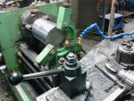
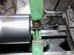
Let's see if this works...

Status
Not open for further replies.

machinist@large

Active member
Messages
2,865
Reaction score
33
Location
West Michigan, 49331
If you're in the market for an engine lathe, how to test drive one is a much larger project than I can cover tonight. On the other hand, I'm hoping I can post up some photos with the appropriate descriptions to show the work arounds I've come up with for the most worn out machine I get to but head's with at work.....
IMG_20141118_104030.jpg

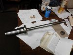
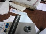
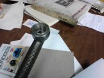
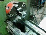
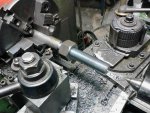
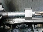
That is a shot of the 2 1/4" ×4 1/2 NC thread I had to cut on the end of a replacement arbor for the shop foundry. The threaded section is 8" long on this end. The other end only had to be threaded 2". The problem is the total length of the shaft finishes at 45". And I have to turn down another 26 1/2"of the shaft by .010".

Did I mention that the ways on this poor machine are basically trashed?
IMG_20141118_104054.jpg

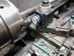
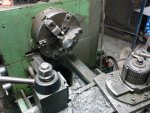
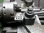
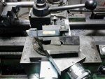
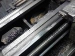
This poor thing is so worn out from neglect that I can only find about an 8" to 10" band in front of the spindle where the wear and tear will let me cut in a straight line. The inverted "V" you see is the front of the bed. And it's shot.

So how do you try to work around this? Tools.
IMG_20141118_115137.jpg

IMG_20141118_115204.jpg

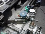
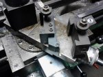
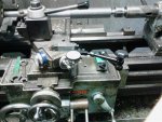
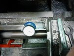
In the above two photos, you see the flat back mounted indicator w/its base on the left (1st pic) and the universal magnetic base with the other on the right, with a mighty mag as the target. The setup on the right is so I can actually see how the cross slide move's, since the dial's are pturny useless for fine work. The second photo shows another angle with the flat back flipped over to show the magnet.

The next two photos show other every day use's for the flat back mount.
IMG_20141118_115305.jpg

IMG_20141118_123459.jpg

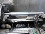
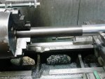
The final straw was trying to turn the other 26 1/2" of the shaft down from 2.250" dia. down to 2.240" dia., +0.000/-.005. The only way was 9" at a time, measuring as I went. What a way to waste a day.....
IMG_20141118_121345.jpg

IMG_20141118_121622.jpg
 

n3480h

New member
Messages
286
Reaction score
2
Location
NW Iowa
Nice work! Most will not realize the level of skill required to maintain tolerance on a long piece with a tight lathe, let alone one so worn it seems to have a mind of it's own. I see the live center, but that's a long piece to cut accurately.
 

machinist@large

Active member
Messages
2,865
Reaction score
33
Location
West Michigan, 49331
Once more into the breach......

OK, on to the next job.

When you work with propeller's, you use a lot of arbor's. The first operation after they leave the foundry is to bore the hub. Almost every other machining operation from then on uses the hub's bore as the starting reference. Which usually means an arbor of some sort.

This is one of the generic ones used in the large propeller polishing area.

IMG_20141120_082531.jpg

If you zoom in closely, you can see that the thread's on the end of the shaft have basically been worn away from literally year's of day in, day out use. The next two are slightly closer pic's, showing the business end of the shaft, as well as what's left of the nut.

IMG_20141120_082521.jpg
IMG_20141120_082512.jpg

The arbor in question is literally machined from one solid piece of steel. Due to time and cost constraints, starting from scratch isn't an option. So, we improvise.

IMG_20141120_082733.jpg

The first order of business was to find/fabricate a new nut. As you can see, the old one is shot. We stock up to 1" in both fine and coarse thread's; to bad this shaft is 1 1/4". So, that's where to start.

IMG_20141120_083155.jpg

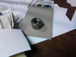
The listed spec's for a 1 1/4”×7 NC nut is 2" across the flat's, 1 1/4" thick. I have the correct tap, but not the thread die for the shaft, so that means the nut has to come first. I need it to gage the thread's I need to cut on the replacement stub shaft.

IMG_20141120_082830.jpg
IMG_20141120_091146.jpg

As a side note, when you have a block type quick change tool post, the easiest way to standardize your setups is to square the post body to the chuck. The easiest way I've come up with is using a 1-2-3 block against the face of the chuck.

IMG_20141120_092727.jpg

I've got more photos, as well as more information, but that's about all the site system will let me load up in one post.

To be continued.....
 

machinist@large

Active member
Messages
2,865
Reaction score
33
Location
West Michigan, 49331
OK, continuing on.

Once I had the new nut complete, I could start on the stub shaft. The only problem was that I'm out of 1 1/4" stock. Happened to trip over (literally) a short piece of 1 3/8" CRS. Not my first choice for material, but since its going to be used in a nasty environment with. 010"+ clearances, all is good.

The first order of business is to thread the end to match the new nut.

IMG_20141120_101606.jpg

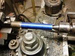
In this photo, I've turned the diameter down to 1.250" for a little over the 6" length I needed to cut thread's on. I've chamfered the end, and relieved the inboard end where I need to stop. I've covered it with layout fluid, and run the trace pass so I could confirm that I have the gearbox set up properly to get the thread count I need (7 thread's per inch).

IMG_20141120_103240.jpg
IMG_20141120_103311.jpg

The above photos show the finished results, being checked with the new nut. After that, it's just a case of turning down the other 18" of the shaft to the final diameters. Flip it around, and part off the chucking stub.

IMG_20141120_135029.jpg
IMG_20141120_135123.jpg

I threw these two pic's in for Fabroman; we've been exchanging PM's about the best way to use a parting tool, as well as better styles. Personally, I have a love/hate relationship with the concept/actual use of these :censored: things; probably because the correct setup and use seems to be the most " Smoke and Mirrors " part of running an engine lathe.
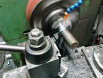
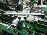
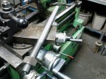
The style I prefer is the top tool in the first photo, on the left in the second. It's a ridgid holder with a replaceable carbide insert. The other one is the really old style HSS parting tool,which I've had abisimal luck with over the year's.

IMG_20141120_135505.jpg

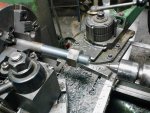
OK, here's the better one; 100 RPM, .0025" IPR feed, flood coolant. Got the job done, but I have really spotty results when it comes to the oh so perfect finish that the suppliers always show in their ads....

And finally, here's the completed stub shaft and nut, ready to be installed in the old hub......

To be continued.....

IMG_20141120_140838.jpg
IMG_20141120_140851.jpg
 

machinist@large

Active member
Messages
2,865
Reaction score
33
Location
West Michigan, 49331
OK, what's wrong with this picture??????

OK, on to the next project....

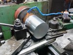
Billet size: 6.5" in diameter by 9" long. Multiple operations to be performed. First was to skin the OD for a minimum clean up so I could set up the steady rest to support the outboard end while I started the ID work....

IMG_20141125_120804.jpg

Then the fun began.....

IMG_20141125_121453.jpg

IMG_20141125_121511.jpg

Needless to say, the factory steady rest has come up short. The part that really bugs me is this is a lathe with a 14" swing over the bed, and ~9" over the cross slide. So why did they feel that the steady rest needed only 5" or less of capacity?!?!?!?!

I'll get around it, it's just going to take more time and work than it should. The fact that this is the newly minted engineers pet project just adds to the frustration level...... :furious2:
 
Status
Not open for further replies.
Top