

nileshc
Member
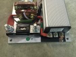
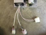
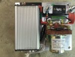
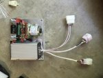
I just bought the kelly controller (KDS36100E) and I am having trouble with figuring out the wiring. I have not added the reverse contactor and the wiring diagram shows the controller having 2 junctions or two connectors but on the actual controller I got there are 3. Here is the link to the wiring diagram and I have a PM Motor
http://kellycontroller.com/mot/downloads/KellyKDSUserManual.pdf
So here are the questions...
1. What is supposed to be wired at junction 2 at wire 5 (white) and wire 10(black)? The hall effect throttle I have only has 3 wires.
2. The key switch that is listed in the diagram, how many volts and amps should the switch handle? 36 volts? since that is the voltage of my motor and batteries
3. How does the wiring of the key switch work? Is it supposed to be connected to the diode?
4. What is supposed to be wired at junction 1 at wire 9(red) and wire 4(green)?
Sorry if the way I explained my issue is hard to understand. I am no expert at understanding wiring diagrams and thanks in advance. I have also added pictures of the wiring diagram and controller.
http://kellycontroller.com/mot/downloads/KellyKDSUserManual.pdf
So here are the questions...
1. What is supposed to be wired at junction 2 at wire 5 (white) and wire 10(black)? The hall effect throttle I have only has 3 wires.
2. The key switch that is listed in the diagram, how many volts and amps should the switch handle? 36 volts? since that is the voltage of my motor and batteries
3. How does the wiring of the key switch work? Is it supposed to be connected to the diode?
4. What is supposed to be wired at junction 1 at wire 9(red) and wire 4(green)?
Sorry if the way I explained my issue is hard to understand. I am no expert at understanding wiring diagrams and thanks in advance. I have also added pictures of the wiring diagram and controller.
Attachments
-
 IMG_6192.jpg354.7 KB · Views: 3
 -
 IMG_6191.jpg359.5 KB · Views: 3
 -
 IMG_6189.jpg362.3 KB · Views: 4
 -
 IMG_6188.jpg358.7 KB · Views: 5

