
VR4
Kilted Kiwi
After seeing several posts about this and having recently completed the restoration of my son's kart I thought I would create a thread on how to connect a kill switch. I have a 1977 Briggs & Stratton engine on my kart FYI.
The switch I used is not waterproof but I don't intend on using it in the rain. It is also wired up the other way around and so when the white dot is switched down, the kart is off. I have since added some dymo labels over the top with OFF and ON so that there is no confusion! Needed to mention this so that there is no confusion when looking at the pics!
We started by removing the wire that is held on the side of the engine by the clip against the copper coloured metal strip in the photos. This is the original kill switch on the motor. Once disconnected, we joined this wire to a length of orange covered wire as shown in the photos. We clamped blue connectors on each end so that we could return it to normal later down the line. You could attach it more permanently by twisting the two wires together and then cover with some heat shrink. This means that there is no kill switch at the back of the engine currently.
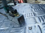
The orange wire was then cable tied along the back of the engine and along one side where it was out of the way and unlikely to get snagged. I brought the cable up under the floor by the steering column. We made a holder for the switch out of some square tubing and grinded out a hole for the switch to rest inside. We did drill part of one end to allow it to rest against the steering column but in the end we set it back by a few cms. It was held into the floor by two screws. THe switch was later held by a couple of screws into the metal tubing.
Looking down on top of the switch as it is shown in the pictures, the earth (yellow,green wire) was attached to the top right screw underneath the switch. The earth already had a metal loop attached to both ends and so we just screwed this on to the top right screw (4 screws in total under the switch but only 2 used). The other end of this earth cable was attached to the steering column via a metal jubilee clip. We filed down the steering column back to bare metal and held the other end of the earth wire (fitted with another metal loop end fitting) directly onto this. Some green insulation tape now covers the clip.
The other end of the orange wire running from the motor to the switch connects to the bottom right screw (looking down on top of the switch) and again had one of those metal hoops cramped onto the end of it before being screwed underneath the switch. The screws down the left side of the switch underneath were not used. We did use a device to measure the current across the swtich initially but following this description you should be ok.
I wanted the switch set up so that my son could switch it off by pressing the switch end closest to him - this works well.
Hope this helps you guys - works a treat. Would be nice to be able to still kill it at the engine end but I can manage without this at the moment!
The switch I used is not waterproof but I don't intend on using it in the rain. It is also wired up the other way around and so when the white dot is switched down, the kart is off. I have since added some dymo labels over the top with OFF and ON so that there is no confusion! Needed to mention this so that there is no confusion when looking at the pics!
We started by removing the wire that is held on the side of the engine by the clip against the copper coloured metal strip in the photos. This is the original kill switch on the motor. Once disconnected, we joined this wire to a length of orange covered wire as shown in the photos. We clamped blue connectors on each end so that we could return it to normal later down the line. You could attach it more permanently by twisting the two wires together and then cover with some heat shrink. This means that there is no kill switch at the back of the engine currently.
The orange wire was then cable tied along the back of the engine and along one side where it was out of the way and unlikely to get snagged. I brought the cable up under the floor by the steering column. We made a holder for the switch out of some square tubing and grinded out a hole for the switch to rest inside. We did drill part of one end to allow it to rest against the steering column but in the end we set it back by a few cms. It was held into the floor by two screws. THe switch was later held by a couple of screws into the metal tubing.
Looking down on top of the switch as it is shown in the pictures, the earth (yellow,green wire) was attached to the top right screw underneath the switch. The earth already had a metal loop attached to both ends and so we just screwed this on to the top right screw (4 screws in total under the switch but only 2 used). The other end of this earth cable was attached to the steering column via a metal jubilee clip. We filed down the steering column back to bare metal and held the other end of the earth wire (fitted with another metal loop end fitting) directly onto this. Some green insulation tape now covers the clip.
The other end of the orange wire running from the motor to the switch connects to the bottom right screw (looking down on top of the switch) and again had one of those metal hoops cramped onto the end of it before being screwed underneath the switch. The screws down the left side of the switch underneath were not used. We did use a device to measure the current across the swtich initially but following this description you should be ok.
I wanted the switch set up so that my son could switch it off by pressing the switch end closest to him - this works well.
Hope this helps you guys - works a treat. Would be nice to be able to still kill it at the engine end but I can manage without this at the moment!
Attachments
-
 kill 1.jpg97.2 KB · Views: 17
-
 kill 2.jpg88.4 KB · Views: 15
-
 kill 3.jpg74 KB · Views: 12
-
 kill 4.jpg73 KB · Views: 11
-
 kill 5.jpg65.2 KB · Views: 20


