Home made,

Status
Not open for further replies.

AdrianH

New member
Messages
12
Reaction score
0
Location
North West UK
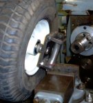
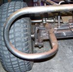
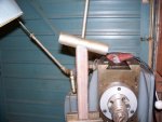
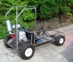
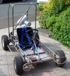
These are two snaps of my home made kart.

Still having some issues finding anywhere to ride. Up to now tried 4 farms and got a no from them.

Took it out of the garage today to help clear some space, and decided to take some snaps with the new camera.

If it runs OK, I may get a modern engine for it as the GX200 is 19 kg lighter then the old G65 presently fitted for same BHP.

Note car exhaust to keep noise down!

Cheers

Adrian

note 2nd go at posting so hope it works!
 

Attachments

  • 600kart1.JPG
    600kart1.JPG
    94.4 KB · Views: 317
  • 600kart2.JPG
    600kart2.JPG
    87.2 KB · Views: 285

RobertD

Administrator
Staff member
Messages
3,019
Reaction score
56
Location
Texas
Great work. And nice pics on your site, too.

Question: these two pics show that the axle is angled in reference to the spindles.. you said that's 8 degrees. Can you take a few shots of the finished frame to spindle connections, and also mention your methods for finding that angle, and also the method for jigging up the the final frame to spindle connections? That's a difficult thing I think people could benefit from.

Can't wait to see some "in action" pics, too!
 

Attachments

  • frontaxle1.jpg
    frontaxle1.jpg
    59.3 KB · Views: 131
  • frontaxle2.jpg
    frontaxle2.jpg
    72.3 KB · Views: 143

RobertD

Administrator
Staff member
Messages
3,019
Reaction score
56
Location
Texas
also, we ride in a large stadium parking lot. They don't seem to mind. I can't imagine that they wouldn't allow it on the beach -- if you can drive a car on it , then what's the difference? maybe they're imagining that you're bringing a dune buggy.
 

AdrianH

New member
Messages
12
Reaction score
0
Location
North West UK
Hi

I suppose it is reasonable easy to get the angles if you have a mill and an adjustable vice to set the number of degrees you want. If not then the task may be difficult.

The plate the axle bolt goes through was set over at an 8 degree angle and drilled through with an end mill near size, then finished off with a drill to size.
The 16 mm bolt then welded into place.

The axle spindle is 1 inch round tube with Delrin lining as a bearing surface.

With the vice still at the same angle I clamped in some 1 inch square tube (part of the frame). Using a 25 mm end mill in the Harrison milling machine, I the cut in to the end of the square tube leaving a profile to accept the round tube. This was welded up when on the rest of the frame.

I guess pictures will help a lot and I will try to do this for the group soon.

Cheers

Adrian
 
Last edited:

AdrianH

New member
Messages
12
Reaction score
0
Location
North West UK
I have been unable to set up in the workshop what I tried to say in the previous post, spent much of the time with brush and shovel cleaning up and ran out of time.

I have taken a picture looking at the front axle and hope this gives a better understanding.

The unfortunate thing is it shows up my poor welding and the rust forming on the steel.

Cheers

Adrian
 

Attachments

  • axlekart.JPG
    axlekart.JPG
    87.2 KB · Views: 115

RobertD

Administrator
Staff member
Messages
3,019
Reaction score
56
Location
Texas
ah, don't fret the welding, you gotta learn somehow! can you describe how you jigged everything up to ensure it was nice and straight and true when you welded the spindles to the frame? thanks!
 

AdrianH

New member
Messages
12
Reaction score
0
Location
North West UK
Managed to set something up tonight and take some pictures so here goes.

no1 shows a plate in the vice which has been set up at 15 degrees so it is more prominent and easy to see.

no2 is just a top view showing how any hole bored through the plate would be at the vice angle.

no3 is with vice at same angle but now holding 1 inch square tube, level with a 1 inch milling cutter.

no4 is the top view showing the positioning

no5 is at end of cut!

What this does is cut the square tube to take the round tube at the 15 degrees angle as set. The burrs are then removed with file, or sanding belt.

no6 shows it with a small piece of 1 inch round tube just sat in the cut groove.

This makes jigging almost non existent, as the angles are all there, a few tack welds hold it all in place whilst the inch square tube is placed on the frame, squared with a measure, held in place with clamps and again tack welded.

Once every this is checked again the the lot is welded up.

When doing both ends of the "steering beam" which was about 27 inches in my case the tube is turned around and rotated so that the cut in is towards the top.

Hope this description helps and is clear.

Cheers

Adrian
 

Attachments

  • no1.jpg
    no1.jpg
    51.2 KB · Views: 62
  • no2.jpg
    no2.jpg
    51 KB · Views: 53
  • no3.jpg
    no3.jpg
    49.9 KB · Views: 41
  • no4.jpg
    no4.jpg
    51.6 KB · Views: 36
  • no5.jpg
    no5.jpg
    52.7 KB · Views: 38
  • no6.jpg
    no6.jpg
    44.1 KB · Views: 44

RobertD

Administrator
Staff member
Messages
3,019
Reaction score
56
Location
Texas
Ahh, I see, the angle is cut into the frame member... Very nice! I was hoping you had some good pics of jigging -- i think a lot of people have trouble with that part.

Looks awesome and good luck again on finding riding space!
 

robin

New member
Messages
584
Reaction score
0
Location
in a house
i use all the things i make on a industreal estate espesaly on a sunday ther are 2 halfmile roads near my house with a huge rounabout at the bottom for artics to turnaround on we never get eny bother from enyone. good luck.
 

AdrianH

New member
Messages
12
Reaction score
0
Location
North West UK
Last edited:
Status
Not open for further replies.
Top