Home built motor controller

Status
Not open for further replies.

kibble

I banned myself
Messages
2,766
Reaction score
1
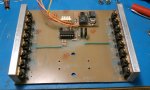
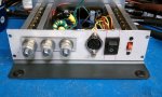
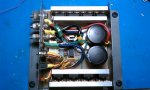
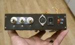
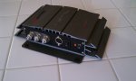
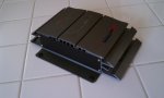
Hey guys, haven't been on here in a while and I figured I'd share one of my projects that I started a couple years ago but never got around to finishing up until a few weeks ago. Some of you might remember me working on a motor controller modeled after an electric scooter motor controller, but heavily beefed up. Well, I'm glad to say that it works great and is quite possibly one of my best looking completed projects to date! I used a case from an old 50W Radioshack amplifier as it was just the right size.

I designed the controller to be able to handle a 500W motor I bought from a fellow site member, as well as modified starter motors, which require even more current. It also has a 36/24V selection switch, which only thing it does is prevent the unit from operating if the batteries drop below a certain voltage to prevent damaging them. The only thing that it doesn't have at the moment is over-current protection, but I designed it with the ability to add that later on. Here's some pics:
 

Attachments

  • cont01.jpg
    cont01.jpg
    367 KB · Views: 48
  • cont02.jpg
    cont02.jpg
    376.3 KB · Views: 55
  • cont03.jpg
    cont03.jpg
    286.5 KB · Views: 42
  • cont04.jpg
    cont04.jpg
    316.9 KB · Views: 36
  • cont05.jpg
    cont05.jpg
    365.5 KB · Views: 44
  • cont06.jpg
    cont06.jpg
    328.4 KB · Views: 39
  • cont07.jpg
    cont07.jpg
    246.5 KB · Views: 33
  • cont08.jpg
    cont08.jpg
    253.5 KB · Views: 30
  • cont09.jpg
    cont09.jpg
    236.7 KB · Views: 21

r97

Measure twice cut once
Messages
3,793
Reaction score
2
Location
Massachusetts, USA
that looks great! well done! i was thinking about making one of those, but its a bit beyond me right now. i was considering getting this kit, or making a more powerful version of it to handle about 7k-9K watts. but that project was to expensive!
 

kibble

I banned myself
Messages
2,766
Reaction score
1
Fortunately I didn't spend much on this as I had plenty of parts from old UPS's that I used, particularly the mosfets. Almost everything else was scavenged from other circuit boards. The aluminum bars that the MOSFET's and diodes are attached to was really cheap at only a few dollars. Only other things I had to buy were the blank circuit board, diodes, nuts and bolts for the high current connections and some of the crimp-on terminals. Hoping to put it to use in a small electric kart of some kind. I have the batteries and everything ready to go, just needs a vehicle. :arf:
 

dan

New member
Messages
330
Reaction score
0
Location
Austraila
awesome well done looks awesome. how do u control the power to the motor though a twist throttle some how?
 

kibble

I banned myself
Messages
2,766
Reaction score
1
It can take a twist throttle with a hall sensor or a potentiometer. It doesn't really matter what it is as long as it can vary the voltage between gnd and 5V at one of the input pins on the round connector. I'll try to get a video of it working.

edit: Video uploaded:

http://www.youtube.com/watch?v=KGXc5gSexoQ
 
Last edited:

kibble

I banned myself
Messages
2,766
Reaction score
1
So I have a pretty good idea of what I'm going to use this setup for. I got a hold of an old, small shopping cart that was gonna be tossed cuz it's kinda rusty and has a broken wheel. Gonna turn it into a kart! :D

It may be a while before I get to this project because I don't have an outlet for my welder yet and I need monies for some parts... :idea2: Fortunately, I really don't need much other than some bearings, an axle and a few other things here and there.
 

The Mechtician

Gargamel Jr.
Messages
183
Reaction score
0
Location
Surrey, BC, Canada
That's some nice electrical work! I never would have thought of salvaging mosfet's from UPS's :p I like the big beefy heatsinks to!

as well as modified starter motors, which require even more current.

What modifications do you speak of? I've got 3 or 4 starter motors sitting in a greasy pile at my parent's place, I'd love to power something with them :2guns:
 

kibble

I banned myself
Messages
2,766
Reaction score
1
That's some nice electrical work! I never would have thought of salvaging mosfet's from UPS's

The small UPS's range in about 2-4 MOSFET's, depending on wattage produced, but some of the bigger one's can have up to 16, which is where I got all these from. The cool thing was that they kept the leads long so it was almost like having a bunch of new ones. Plus it was awesome that they were all N-type.

What modifications do you speak of? I've got 3 or 4 starter motors sitting in a greasy pile at my parent's place, I'd love to power something with them :2guns:

http://www.diygokarts.com/engine/car-starter-motor-conversion.html

That's what I did, I actually wrote those instructions and Robert posted them on the main site. :D

The hardest part is the output from the starters and rigging something to them to drive the wheels. It would be a lot easier on a starter that has the reduction gears, although slower. I actually haven't used a modified starter on anything yet.
 

The Mechtician

Gargamel Jr.
Messages
183
Reaction score
0
Location
Surrey, BC, Canada
That is super cool! Thanx for pointing that out, I'll definitely be hacking some starters in the future! I've got both direct drive and gear reduction units, but like you said I'm still trying to wrap my head around how to adapt them to actually turn something. Still, very cool!

This may sound like a stupid question, and purely hypothetical, but let's say I wanted to drive all 4 wheels of a kart with electric motors. Would it be possible to build a motor controller that can manage 4 motors? They don't need to change speed independently of each other, in fact they should all be turning the same speed all the time, but I have no idea if it's possible in the first place. I'm a millwright, not an electrician, so my electrical knowledge only goes so far! lol! Thanx!
 

kibble

I banned myself
Messages
2,766
Reaction score
1
let's say I wanted to drive all 4 wheels of a kart with electric motors. Would it be possible to build a motor controller that can manage 4 motors? They don't need to change speed independently of each other, in fact they should all be turning the same speed all the time, but I have no idea if it's possible in the first place. I'm a millwright, not an electrician, so my electrical knowledge only goes so far! lol! Thanx!

It's not impossible, the motors would just have to be pretty identical so you don't have one wanting to rotate faster or slower than the rest. It would either have to be a controller that can handle a massive amount of current if the motors are connected in parallel, or one that can handle higher voltage, which would be ideal as it wouldn't need to handle as much current and the motors could probably be connected in series. My controller can only do a maximum of 50V as that's what the MOSFET's are rated for, and even then I'd have to modify some of the internals as some of the parts can't go that high, particularly the dc-dc regulator inside for the low voltage parts and the MOSFET driver transistors. I was originally going to put a switch on this controller for 24/36/48V, but decided not to as the 48V would complicate things a bit and plus I didn't have anything that would take that high of a voltage.
 

oscaryu1

New member
Messages
2,767
Reaction score
0
KIBBLE YOU'RE BACK :DDDDDDDDDD

If you don't mind me asking, where exactly did you learn all of this? O_O

The motor controllerz always confounded meh. It'd be nice to understand how exactly they work/how they're built.

OBTW - Would you recommend stacking FET's to increase teh amount of amperage they can flow?
 

kibble

I banned myself
Messages
2,766
Reaction score
1
KIBBLE YOU'RE BACK :DDDDDDDDDD

If you don't mind me asking, where exactly did you learn all of this? O_O

I've been messing around with electronics since I was little. I never really had any toys because I took everything apart to figure out how it worked. :eek: Those electronics kits that they sell at Ratshack, like the 200 in 1 and whatnot, can be quite helpful in learning the basics. I used to have one but I ended up taking it apart and using the parts from that to build other things. I didn't start learning more of this stuff until we got the internet back in 1996. Then I was looking up parts and datasheets for components and learning about how those worked. You just gotta start messing with things. You may fry some components every once in a while, but at least you learn what not to do next time.

The motor controllerz always confounded meh. It'd be nice to understand how exactly they work/how they're built.

I made a schematic that I posted up with one of my old threads that I drew up from reverse engineering a Chinese scooter motor controller, then all I did was beef up the output. I'll have to look for it though cuz I don't remember exactly where I had it.

OBTW - Would you recommend stacking FET's to increase teh amount of amperage they can flow?

That's pretty much all I did, so instead of using one FET for the motor, there's 16 in parallel. I had to upgrade the FET driver also with some higher current transistors to be able to handle driving 16 FET's.
 

oscaryu1

New member
Messages
2,767
Reaction score
0
Sweet =]

After agooglin' a bit, I'm assuming that the FET driver is an entire bunch of electronics that'll possibly need upgrading? (Need it to flow more amperage, not boosting voltage over its stock rating :))
 

kibble

I banned myself
Messages
2,766
Reaction score
1
Nah, well, you CAN, but all I did was use two transistors that could handle more power than the stock ones and changed the resistors that form the voltage divider at their base to keep the voltage going through them at an acceptable level.
 

oscaryu1

New member
Messages
2,767
Reaction score
0
I was lost at voltage divider XD

I was wondering if I could PM you with some slightly more "in depth" questions? :)
 
Status
Not open for further replies.
Top