Comet 40 sheaves too far apart?

Status
Not open for further replies.

BoogieBob

New member
Messages
15
Reaction score
10
We have a Fox Phantom Pro with a Subaru 10hp Robin and a Comet 40.

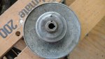
I pulled the driven part of the converter off, cleaned and lubed per spec but noticed that the distance between the fixed and movable sheaves is greater than the Comet diagram by about 3/16".
Am I correct in my assumption that the sheaves should be just slightly wider than the belt to allow the belt to ride on the brass bushings during idle?

I'm a former master mechanic (MANY years ago), but I'm unfamiliar with go-kart systems.

Prior to removing the converter, the go kart ran fine overall, but you had to rev the engine up more than expected before the converter would engage, so I wonder if this is due to the sheaves having to move farther before engaging the belt.

I have triple checked that it is the proper belt, and I assembled the converter properly (it was already assembled properly). I tried removing one of the bronze bushings but then the sheaves were touching the belt.

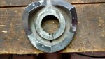
Any ideas? I have a couple of pics which may be helpful.


Many thanks,
Bob
 

bob58o

SuckSqueezeBangBlow
Messages
9,646
Reaction score
1,865
Location
Chicago-town USA
but noticed that the distance between the fixed and movable sheaves is greater than the Comet diagram by about 3/16".

The diagram I have shows 2-1/8" spacing on the DriveR Unit.
Meaning the sheaves are closer in the pic than they are in the diagram, right?
Notice the measurements 3-7/8" and 1-3/4", leaving 2-1/8".
 

Attachments

  • 40 s.jpg
    40 s.jpg
    91.7 KB · Views: 7
  • 40s2.jpg
    40s2.jpg
    375.4 KB · Views: 2

Whitetrashrocker

Inmate #952016
Messages
5,224
Reaction score
4,723
Location
Southern New Mexico
Your pics looks like how my 40 sits at rest.

There are also 3 different weights and 2 different springs that go inside that TC. This greatly effects the engagement rpm.

Could you open it up and take a pic to show us the innards?
 

BoogieBob

New member
Messages
15
Reaction score
10
Interesting.

My diagram for the 40 shows 2-3/16 for the outer sheave assembly and 3-15/16 total from outer nut to inner sheave. This leaves 1-3/4".

My measurement of the outer sheave assembly is just a hair under 2-3/16".

Also, I just measured more carefully: the distance from the inner sheave to outer is exactly 1-7/8", or 1/8 wider than spec.

But, maybe this is ok. The sheave has to move 1/8" before it touches the belt...

I will try to get a pic of the inner weights and springs.

Bob

Ps. The kart is a BLAST!
 

Whitetrashrocker

Inmate #952016
Messages
5,224
Reaction score
4,723
Location
Southern New Mexico
I don't think I'd worry about a little discrepancy.
When I assembled mine I have 2 bronze bushings then a snap ring, then a third bronze bushing, the spring and then a 4th bronze bushing. Then the moveable sheave goes on. I put the 4th bushing in the movable/cover unit before flipping it on the hub and screwing it together.
 

Attachments

  • IMG_20170202_145851178.jpg
    IMG_20170202_145851178.jpg
    244.5 KB · Views: 3
  • IMG_20160914_092150131.jpg
    IMG_20160914_092150131.jpg
    132.9 KB · Views: 2
  • IMG_20160420_131652632.jpg
    IMG_20160420_131652632.jpg
    255 KB · Views: 3

BoogieBob

New member
Messages
15
Reaction score
10
I don't think I'd worry about a little discrepancy.
When I assembled mine I have 2 bronze bushings then a snap ring, then a third bronze bushing, the spring and then a 4th bronze bushing. Then the moveable sheave goes on. I put the 4th bushing in the movable/cover unit before flipping it on the hub and screwing it together.

Yes!

That is identical to mine.

I'm probably fretting over nothing.

Many thanks for the help. I've learned a lot over the last year just lurking on this site.

Torque converters, engines, Ackerman angle, etc. Good stuff.
In the near future, I'll probably be hitting you guys up for advice on various repairs, mods, etc. As a former mechanic and chronic tinkerer, I just can't leave anything alone.

My 9 year old son, 4 year old daughter, wife, sister, family and friends all love zipping around the property on that kart.

This is my son:


Take care,
Bob
 

Whitetrashrocker

Inmate #952016
Messages
5,224
Reaction score
4,723
Location
Southern New Mexico
Here's some free tuning. Just need a drill and a protractor.

On the 30 series there are 3 holes on the driveN unit for spring preload.

The 40 series does not have these holes. So I made some.
I took the driven unit apart and set my protractor on center best as my eyeballs could. Then marked 45° either side of the hole. Drilled them out and voilà a tunable driveN unit.

Less spring preload will result in an easier upshift.
More spring preload will result in a delayed upshift. This is the way I moved mine. Keeping it in a lower gear makes for more wheel spinning fun.

Now this doesn't change top speed or anything, just the engagement time.

Have fun tinkering!
 

Attachments

  • IMG_20170820_121255213.jpg
    IMG_20170820_121255213.jpg
    182.4 KB · Views: 2
  • IMG_20170820_123647736_HDR.jpg
    IMG_20170820_123647736_HDR.jpg
    283.2 KB · Views: 2
  • IMG_20170820_124558316.jpg
    IMG_20170820_124558316.jpg
    284 KB · Views: 2
  • IMG_20170820_125111437.jpg
    IMG_20170820_125111437.jpg
    207.8 KB · Views: 2
Status
Not open for further replies.
Top