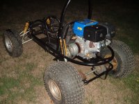
Full Suspension Big Block Mini-Buggy Build

SquidBonez

Active member
Messages
502
Reaction score
114
Location
New Jersey, USA
If your steering is going to work the way I think it will. When you turn left it will go right. And visa versa.
The spindles are a trailing spindle arm design (like any race kart really). So when you turn left, the pitman arm on the shaft pushes the left linkage out, which pulls the left spindle in, causing the left tire to point away from the frame. On the right side, it pulls the right linkage in, which pushes the right spindle out causing the right tire to point towards the frame. All the linkages do is reverse the input of the steering shaft. If I didn't have the linkages, then when I turn left the buggy would go right and vice versa. Again, sort of hard to explain through text but once it goes together you'll get a better idea.
 

Denny

Canned Monster
Messages
8,499
Reaction score
4,732
Location
Mayberry, Indiana
I’ll have to see it. Other wise I’ll have to still stick to my position of steering backwards. I’m not trying to put you down. Sometimes builders know more then the onlookers. I do like you using all the bushings. Might as well drill them and put in grease zerks while you are at it.
 

SquidBonez

Active member
Messages
502
Reaction score
114
Location
New Jersey, USA
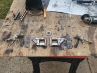
Got the a-arms done today after a few tries.
20211218_142908.jpg
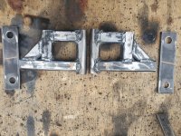
While they are rather short I'm only looking for 4" of suspension travel on the front, which I'm confident I'll get considering my shocks themselves have about 2.5" of travel. The pieces of flat bar are what the spindles are going to bolt to after I weld them to the arms. I'm going with 10° of caster angle (which is the slanted line you see drawn on them). I'm probably going to make two more of those bars with holes in them and weld them together just for extra strength since I don't think they will be strong enough on their own (even though they are 1/4" thick). Couldn't hurt. Here's a closer picture:
20211218_142925.jpg
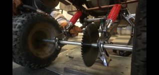
As for the rear suspension, I think I've come up with a good solution that allows me to get the engine off the swingarm and also keep the wheelbase short. I'm going with a system very similar to this:
Screenshot_20211218-195311_YouTube.jpg
The engine will simply be mounted higher off the back of the frame. It needs to be high enough so the rear swingarm doesn't hit the engine plate but low enough to keep the center of gravity down. The engine will drive a jackshaft that also acts as the pivot point of the swingarm, thus keeping correct chain tension at all times. I'm still adding a tensioner for this second chain (which is the sprocket you see in the first picture) to account for chain stretch. This will make the ride much smoother and also allow me to take bigger jumps without worrying about damaging the engine.
 

SquidBonez

Active member
Messages
502
Reaction score
114
Location
New Jersey, USA
Been getting some measurements for the rear suspension now that the front is just about done. While doing some digging I found a thread from 2012 on a different site about a user converting (ironically) his old Manco Dingo into a full suspension buggy, and he did the rear suspension almost the exact same way I plan on doing mine now.
Picture147.jpg
I'll link to the thread at the end of this post since there's a lot of good info there. But he did mention something that was worrying me. Notice how high the engine is mounted on that buggy of his? That's due to the swingarm. If he mounted it lower, the swingarm would hit the engine mount under full bump. So my plan is to copy his; raise the engine up by about a foot to clear the swingarm, but not too much higher since I want to keep the center of gravity as low as possible. Might also have to put some form of bump-stops on the rear just in case. I'm estimating the wheelbase to be between 58" - 59" with this design which is within my goal of 60" maximum. This design is still more complicated than just mounting the engine on the swingarm, but it will provide way better suspension...as well as help with..."future plans." More on that later. ;^)

Link to thread:
 
Last edited:

SquidBonez

Active member
Messages
502
Reaction score
114
Location
New Jersey, USA
The engine height did not seem to be a problem for him. Reduces unsprung weight too for faster suspension reaction.
That's the main reason why I want to do it. I want this thing to be able to jump and not damage the engine in the process. One thing that I realized is that my build is going to be wider than his as well as sit lower, which will help with stability anyway.
 
Last edited:

SquidBonez

Active member
Messages
502
Reaction score
114
Location
New Jersey, USA
Finally finished the front a-arms! Here is one of them installed:
20211223_135730.jpg
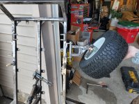
I set the caster to 10° which should be fine. All that's left to do is round off some sharp edges and add a gusset between the flat bar that the heims bolt through and the a-arm itself. Also threw the tire on it for fun and found out that this thing has a decent amount of angle!
20211223_142007.jpg
I'm estimating about 4" - 5" of suspension travel on the front. The back will likely be 5" - 6". Camber is fully adjustable thanks to the heim joints. Everything pivots very smoothly thanks to those bronze bushings. I'm pretty happy with how it came out considering that this was going to be the most difficult part of the build.
 

SquidBonez

Active member
Messages
502
Reaction score
114
Location
New Jersey, USA
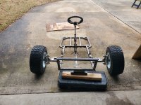
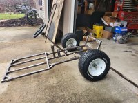
Finished up the a-arms (minus shock mounts) by adding gussets and rounding off any sharp edges. Here it is with both front tires sitting on the ground. Just waiting for my tie rods to come in and I'll have full steering.
20211231_143728.jpg
20211231_143738.jpg
Also used some cheap paint pens on my tires to make the lettering stand out. I think it looks pretty good.
20211230_184033.jpg
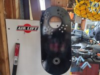
Last but not least, I painted and clear coated the 40 series backplate. There's a few runs but I don't really care too much. This buggy is very obviously built in some dude's garage so I think it kinda adds to the DIY vibe...at least that's what I'll tell myself.
20211231_144814.jpg
 

madprofessor

"Loose Cannon Creations"
Messages
2,899
Reaction score
888
Location
Jacksonville, Florida
A careful wet-sanding with #600 sandpaper will hide most of that runny finish, and a buffer will shine it right back up from the wet-sanding.
Yes, I do watch a lot of hotrodding and customizing shows on my TV. It's my therapy companion.
 

SquidBonez

Active member
Messages
502
Reaction score
114
Location
New Jersey, USA
My tie rods came in and proved all of my main concerns correct. 1.) That the bump steer would be very noticeable/unacceptable. 2.) The tie rods I ordered are too long. 3.) I don't have enough steering angle when all the links are connected. Luckily, all these issues can be fixed.

1.) Rather than make the same mistake I made before and modify the links themselves, I'm going to simply have a piece of flat bar that will connect the ends of both steering links as well as connect to the spindles via tie rods. Here's an example of a similar system off of a snowmobile to get a better picture:
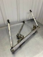
images.jpeg-7.jpg
This will allow me to get the pivot point of the tie rods in-line with the pivot point of the a-arms.

2.) The tie rods can simply be chopped down and re-welded.

3.) I can drill holes in the spindle arms that are closer to the kingpin to increase steering angle.

Hopefully all of these ideas solve my issue because I really want to get this steering done. This is by far the most complicated part of the build, especially considering this is my first time building anything.
 
Last edited:

Denny

Canned Monster
Messages
8,499
Reaction score
4,732
Location
Mayberry, Indiana
You can reduce some bump steer by using long tie rods. With the single A arm design front end, (like fords twin I beam suspension) bump steer is built into the design. Nature of the beast kind of thing. Longer A arms will help also.
 

SquidBonez

Active member
Messages
502
Reaction score
114
Location
New Jersey, USA
You can reduce some bump steer by using long tie rods. With the single A arm design front end, (like fords twin I beam suspension) bump steer is built into the design. Nature of the beast kind of thing. Longer A arms will help also.
True but there are ways to get it to negligible amounts of bump steer. My setup has plenty of room for improvement. The a-arms can't really be any longer than they currently are as I want to keep the front track width smaller than the rear. Currently the front is about 46" and the rear is 50". I just hate the look of buggies/karts where the front is wider than the rear.

My plan is to get the pivot points of the tie rods closer to the pivot of the a-arms and space out the tie rods themselves so they sit parallel to the a-arms. This should - in theory - massively reduce my bump steer. Then again, I'm only dealing with 4" - 5" of suspension travel on the front (I'm guessing).
 

SquidBonez

Active member
Messages
502
Reaction score
114
Location
New Jersey, USA
Another update. Looks like I'm going to have to go double a-arm after all. Looks like you were right, Denny. The distance between the spindle and the steering bar I just made shrinks as the suspension compresses, causing the tires to toe in far too much than what I consider acceptable. The only way to fix this is true double a-arm.
20220106_190559.jpg
Luckily, it doesn't seem like it's going to be too hard of a fix. It does mean the a-arms are scrap, though...
 
Last edited:

SquidBonez

Active member
Messages
502
Reaction score
114
Location
New Jersey, USA
Just remember the upper A arm needs to be shorter by a little. Time to break out the old C.A.D. (Cardboard Aided Design)
Is that true? I thought a shorter upper arm means you get camber gain upon compression but identical length arms means you have zero camber gain?
 

Denny

Canned Monster
Messages
8,499
Reaction score
4,732
Location
Mayberry, Indiana
You should gain some negative camber when turning. Which is good, negative camber helps you turn especially off road. But! Too much will wear the inside of the tire. GM was the first to figure it out in the 50s.
 

SquidBonez

Active member
Messages
502
Reaction score
114
Location
New Jersey, USA
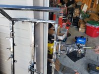
Started to chip away at the project again. I've been a little busy recently. Today I got the supports for where the top a-arm bracket is going to mount to. Also weighed the frame again, we're up to 55 pounds.
20220112_182545.jpg
 

madprofessor

"Loose Cannon Creations"
Messages
2,899
Reaction score
888
Location
Jacksonville, Florida
Good call on the quick-release for the steering wheel, I've got 3 of that type. Slips right on without any difficult lining up like another one I have with a single point that has to line up. You may find when it's finished that you want to get a larger diameter steering wheel though. That 10 degrees of caster will straighten you out at speed very well, but may make it a bear to turn with a little 10" steering wheel.
 
Top